A while ago, I was asked to examine the feasibility of generating closed-loop control waveforms needed for operation in transition mode using the TI UCD3138 controller. These digital controllers are very flexible and equipped with a lot of bells and whistles. I was curious to see what I could come up with.
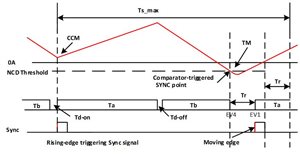
Figure 1: Transition mode control
Transition-mode waveforms do not look like the typical pulse-width modulation (PWM) waveforms, since both the duty cycle and the switching period are changing. They are also not like LLC or phase-shifted waveforms supported by the UCD3138. Therefore, none of the standard modes of PWM output modulation will generate what we need.
What is unique about transition-mode control is that you should start the next switching cycle on time based on what happened in the previous switching cycle – not sooner and not later. This on-time switching of next-pulse ON provides one of the following two advantages:
- Valley switching. Turn off the field-effect transistor (FET) just when the current crosses the zero line and start the next switching cycle after a measured and fixed delay. The voltage should be quite low at that point, avoiding large switching losses.
- Zero voltage switching (ZVS). Turn off the FET just after the current crosses the zero line. The current will be slightly negative; this way, after a certain controlled time delay, the voltage will decay to zero. You could turn the FET on again and start a new switching cycle. But the delay time is a function of Vin and Vout, so it needs periodic adjustment.
On the face of it, both of these ideas seem to be easy to implement with a digital controller like the UCD3138. It has several analog comparators with adjustable reference voltages that can dictate when to terminate the pulse driving the FETs.
Being a microcontroller and firmware-based device, the firmware can adjust the reference to the analog comparator and regulate the delay based on the analog-to-digital converter (ADC) measurement of input and output voltages and currents.
But how can we terminate a pulse and start a new cycle when an analog comparator toggles? Termination of the pulse resembles the cycle-by-cycle (CBC) or peak-current mode (PCM) current limiting by pulse truncation. Should we use the CBC mechanism that already exists in the UCD3138? How do we end the switching period and start a new pulse? The sync input signal can do that, but can it truncate the pulse as well? After all, if a sync event happens when the digital PWM output is high, it will cause a pulse extension; the pulse will stay high until the next switching cycle. Should we connect the analog comparator to both CBC and sync signals?
Here’s a trick that will eliminate the need for CBC: Configure Event4 (EV4) as zero or a very small number at the beginning of the switching period. This way, the sync signal terminates the switching cycle and resets the digital PWM counter. EV4 is engaged immediately after this reset; therefore the pulse is truncated as well. It’s like killing two birds with one stone.
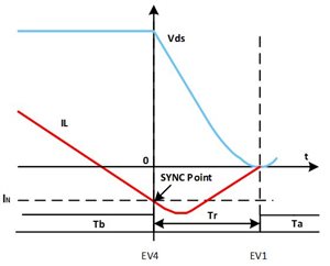
Figure 2: Transition mode current and voltage waveforms
Now we need a delay to let the negative current decay and the voltage go to zero, and then turn the primary FET on exactly at this time in order to achieve ZVS. This time interval between the end of the period and the time to turn on the FET can be achieved by calculating the placement of Event1 (EV1).
Based on calculations, the delay time between end of the period/the start of a new pulse (Tr) and the negative current detection threshold (IN) can be calculated by:
When Vin ≤ Vo/2, no negative current is needed.
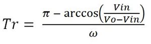
where IN = 0 and ω = 245 nS.
When Vin > Vo/2, a negative current IN is needed to allow the value of Vds to reach zero volts at the valley point.
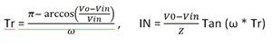
I used a spreadsheet to generate a lookup table that I entered later as part of the firmware to adjust the value of Tr and IN accordingly.
The above look-up table is a simplified way of transition-mode control implementation using the UCD3138. If you use external comparators for current crossover detection, you are all set. But the UCD3138 happens to have several internal analog comparators. How can we utilize one of those comparators for this application?
The problem is that most members of the UCD3138 family of controllers do not offer an external analog comparator output. So the analog comparator output cannot connect to the SYNC pin directly. I was able to come up with a workaround to overcome this, but I will save you from the details here.
Zooming out to see the bigger picture, we have actually implemented many topologies and configurations that were not envisioned by the systems or design group when they defined and designed the UCD3138.
Yet the flexibility of this digital controller allows us to use it in applications, such as a solar micro-inverter, a bi-directional automotive DC/DC, a totem-pole power factor correction (PFC) and much more.
In case you are interested in getting more details for implementing, such as a transition transition-mode scheme using a UCD3138 controller or discussing the feasibility of any other configuration besides the ones already announced and published by TI’s power management group, please comment on this blog. For all TI digital power products and solutions, visit: www.ti.com/digitalpower