Sometimes it’s impossible to find an amplifier with the right input and output characteristics, but a signal chain approach described in my previous blog posts on high gain, high bandwidth works well. Although very high gain can be achieved, one limitation of this approach is the limited DC accuracy. For application where DC accuracy is a must have, creating a composite amplifier is the best approach.
A composite amplifier is an amplifier made of separate elements with non-ideal properties where the end result takes the best of both elements and combines them together. Let’s consider the first amplifier, the OPA188. It is an excellent auto-zero amplifier, but has a major limitation in that its gain bandwidth product is only 2MHz, limiting both the maximum gain and the achievable bandwidth. Auto-zero amplifiers are usually used in high gain application with very limited bandwidth where excellent DC-accuracy, and in particular, offset drift is necessary. The high gain requirement by itself increases the DC accuracy requirement. The open-loop gain characteristic of the OPA188 is shown below in figure 1.

Figure 1: OPA188 open-loop gain and phase
To create the composite amplifier, I added a second stage using an ideal amplifier to the OPA188, see figure 2 below.
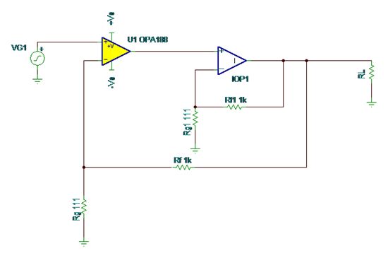
Figure 2: Composite amplifier with OPA188 as first stage and ideal amplifier as 2nd stage
The second stage, when placed in the loop of the OPA188, will increase the open-loop gain by its gain. Note that I have opted to use 20dB for the second stage. I have also placed the composite amplifier in a non-inverting 20dB gain configuration. The resulting open-loop gain and phase of the composite amplifier can be seen in figure 3 below.

Figure 3: composite amplifier open-loop gain and phase
The composite amplifier will now have higher slew rate and higher gain bandwidth product. You will also notice that it is not going to be unity gain stable any more but must be operated at a minimum gain. Since the second stage is ideal, it will not introduce any phase shift in the phase of the composite amplifier.
Stay tuned for my next blog where we’ll cover the selection of the second stage and evaluate the performance of the entire circuit. In the meantime, check out my high gain, high bandwidth series that will hopefully help you solve some design challenges.
High gain, high bandwidth…how can I get it all?
High gain, high bandwidth…why is this circuit oscillating?
High gain, high bandwidth…putting it all together