Achieving a small power rail solution size is one of the highest priorities for embedded system engineers, especially for those designing industrial and communications equipment such as drones or routers. Compared to models released a few years ago, currently available drones are much lighter and have smaller fuselages, while routers are now more portable and compact with a built-in power adapter. As equipment size shrinks, engineers are looking for ways to shrink the power supply solution. In this technical article, I’ll provide a few tips to help you make your power rail design smaller, while demonstrating how to resolve the resulting thermal performance challenges.
Shrinking the package
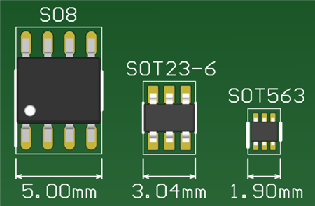
One obvious way to reduce your solution size is to choose an integrated circuit (IC) in a smaller package. Small-outline (SO)-8 and small-outline transistor (SOT)-23-6 packages are common for 12-V voltage rail DC/DC converters. They are typically very reliable. However, if you work in an industry where every millimeter counts – such as the drone market – you may be looking for an even smaller DC/DC converter. The SOT-563 package is almost 260% smaller than the SOT-23-6, and 700% smaller than the SO-8 package. Figure 1 compares the size of the mechanical outline of all three packages.
![]()
Figure 1: Mechanical outline sizes of three converter packages
Apart from choosing a smaller package, another approach to reducing your solution size is to reduce the output inductor and capacitor. Equations 1 and 2 calculate the output inductance (LOUT) and output capacitance (COUT)
![]()
where ris defined as the ratio of current ripple of inductor, VRIPPLE is the maximum allowed peak-to-peak ripple voltage and fsw is the switching frequency of the converter. Because LOUT and COUT are both inversely proportional to fsw, the larger the switching frequency, the smaller the LOUT and COUT. Smaller inductance or capacitance means engineers can select an inductor or a capacitor of a smaller size. Converters with a higher fsw can work with these smaller inductors and capacitors.
Addressing thermal performance
A smaller system faces more significant thermal performance issues, given the limited path for heat dissipation. To effectively solve any possible thermal issues and achieve higher efficiency, you can apply converter switches with a lower RDS(on). Equation 3 calculates the temperature rise on a DC/DC converter:
where PLOSS is the total power loss of the converter and RΘJA is the junction-to-ambient thermal resistance.Consider a 2-A load converter with an average RDS(on) change from 100 mΩ to 50 mΩ. The power loss of this device will result in a 200-mW decrease, which will bring a 16°C cooldown on a typical SOT-563 board with a thermal resistance of 80°C/W. Therefore converters with a lower RDS(on) offer better working conditions at a lower temperature.
Turning theory to practice
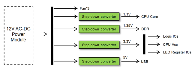
A real-world embedded system often applies multiple step-down DC/DC rails. Figure 2 shows a block diagram of a home router power-stage architecture that needs four lower voltage rails. Let’s take three typical devices applied in this type of system to demonstrate how package size and switching frequency affect power rail solution size.
Figure 2: Power-stage architecture of an embedded system
The
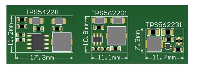
TPS54228 has a 700-kHz frequency in an SO-8 package. The
TPS562201 has a 580-kHz frequency in an SOT-23-6 package, and the
TPS562231 has a 850-kHz frequency in an SOT-563 package. The
TPS562231 has the highest frequency and the smallest IC package size. This solution size is about 142% smaller than the
TPS562201, and 227% smaller than the
TPS54228, as illustrated in Figure 3.
Figure 3: Solution sizes of converters with different packages
The R
DS(on) of the integrated metal-oxide semiconductor field-effect transistor (MOSFET) in the
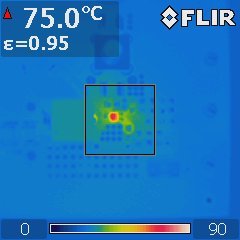
TPS562231 is 95 mΩ (high side) and 55 mΩ (low side). Figure 4 is a thermal image of the full load temperature rise of a 12-V input on the
TPS562231 evaluation board.
Figure 4: Thermal image of the TPS562231 with a 12-V input voltage
In general, the
TPS562231 works in an 850-kHz switching frequency sealed in a small SOT-563 package, which can help reduce the overall solution size. Its low on-resistance also allows for good thermal performance. It’s suitable for routers, drones, set-top boxes or any other embedded designs that require small solution sizes.
Additional resources
![]()