When you can create automotive applications that do more with fewer parts, you’ll reduce both weight and cost and improving reliability. That’s the idea behind integrating electric vehicle (EV) and hybrid electric vehicle (HEV) designs with a combo-box architecture.
What’s a combo-box architecture?
A combo-box architecture integrates powertrain end equipment such as the onboard charger (OBC), high-voltage DC/DC (HV DCDC), inverter and power distribution unit (PDU). It’s possible to apply integration at the mechanical, control or powertrain levels, as shown in Figure 1.
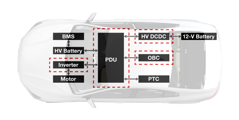
Figure 1: An overview of the typical architecture in an EV
Why is a combo-box architecture great for HEV/EVs?
Integrating powertrain end-equipment components enables you to achieve:
- Improved power density.
- Increased reliability.
- Optimized cost.
- A simpler design and assembly, with the ability to standardize and modularize.
Current combo-box applications on the market
There are many different ways to implement a combo-box architecture, but Figure 2 outlines four of the most common approaches (using an onboard charger and a high-voltage DC/DC combo box as the example) to achieve high power density when combining the powertrain, control circuit and mechanics. The options are:
- Option No. 1 with independent systems; not as popular today as it was several years ago.
- Option No. 2 can be divided into two steps:
- Share the mechanical housing of the DC/DC converter and onboard charger, but split the independent cooling systems.
- Share both the housing and cooling system (the most common choice).
- Option No. 3 with control-stage integration is currently evolving to Option No. 4.
- No. 4 has the best cost advantage because there are fewer power switches and magnetic components in the power circuit, but it also has the most complex control algorithm.
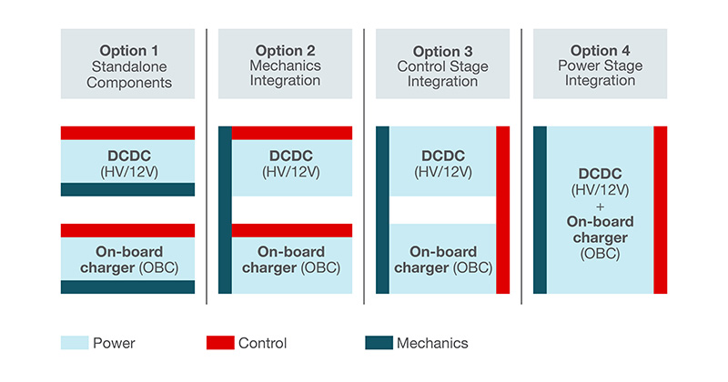
Figure 2: Four of the most common options for a OBC and DC/DC combo-box architecture
Table 1 outlines combo-box architectures on the market today.
High-voltage three-in-one integration of OBC, high-voltage DC/DC and PDU optimizing electromagnetic interference (EMI) | Combo-box architecture integrating an onboard charger plus a high-voltage DC/DC converter | 43-kW charger design integrating an onboard charger plus a traction inverter plus a traction motor (option No. 4) |
*Third party data reports that designs such as this can achieve approximately a |
(one microcontroller [MCU] control power factor correction stage, one MCU control DC/DC stage and one high-voltage DC/DC) |
(one MCU control power factor correction stage, one MCU control DC/DC stage and one high-voltage DC/DC) |
Table 1: Three successful implementations of a combo-box architecture
Combo-box block diagrams for powertrain
Figure 3 depicts a powertrain block diagram implementing a combo-box architecture with power-switch sharing and magnetic integration.
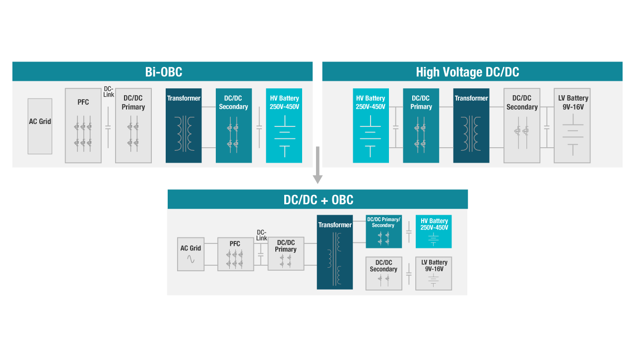
Figure 3: Power switch and magnetic sharing in a combo-box architecture
As shown in Figure 3, both the OBC and high-voltage DC/DC converter are connected to the high-voltage battery, so the rated voltage of the full bridge is the same for the onboard charger and the high-voltage DC/DC. This enables power-switch sharing with the full bridge for both the onboard charger and the high-voltage DC/DC.
Additionally, integrating the two transformers shown in Figure 3 achieves magnetic integration. This is possible because they have the same rated voltage at the high-voltage side, which can eventually become a three-terminal transformer.
Boosting performance
Figure 4 shows how to build in a buck converter to help improve the performance of the low-voltage output.

Figure 4: Improving the performance of the low-voltage output
When this combo topology is working in the high-voltage battery-charging condition, the high-voltage output will be controlled accurately. However, the performance of the low-voltage output will be limited, since the two terminals of the transformer are coupled together. A simple method to improve the low-voltage output performance is to add a built-in step-down converter. The trade-off, however, is the additional cost.
Sharing components
Like the OBC and high-voltage DC/DC integration, the voltage rating of the power factor correction stage in the onboard charger and the three half bridges is very close. This allows power-switch sharing with the three half bridges shared by the two end-equipment components, as shown in Figure 5, which can reduce cost and improve power density.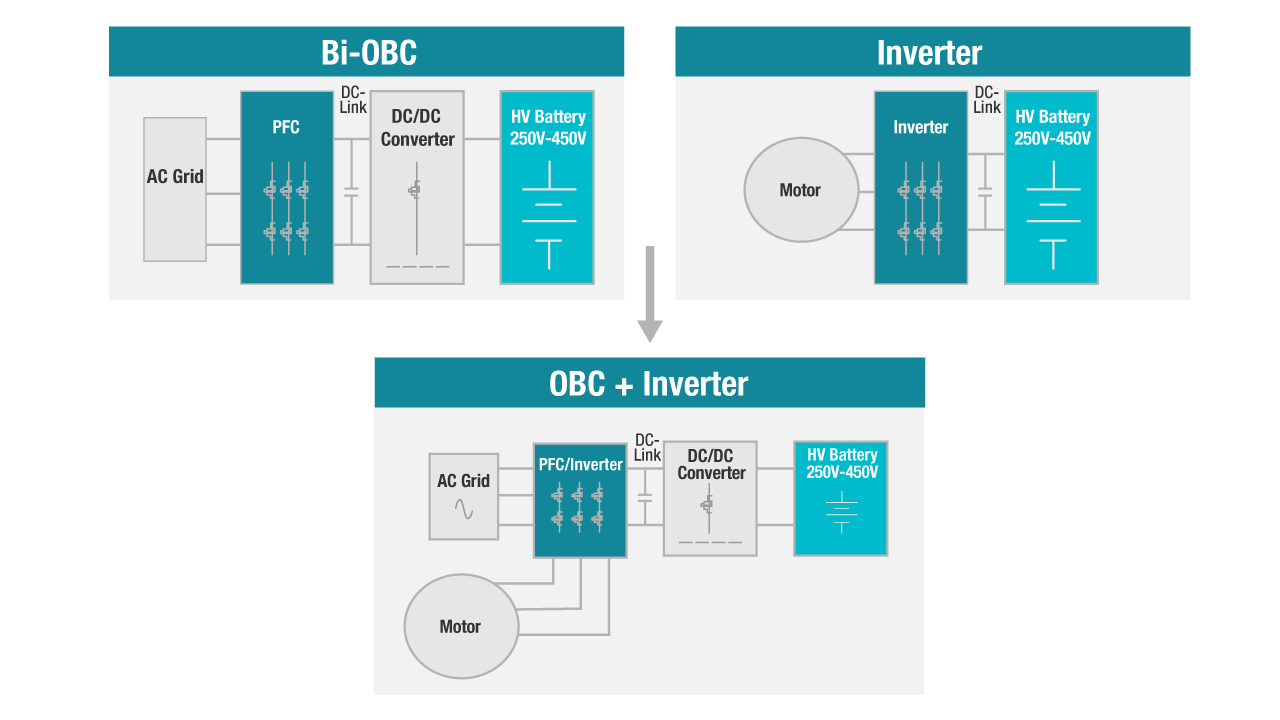
Figure 5: Sharing components in a combo-box design
Since there are normally three windings in a motor, it is also possible to achieve magnetic integration by sharing the windings as the power factor corrector inductors in the OBC which also lends to the cost reduction and power-density improvement of this design.
Conclusion
The integration evolution continues, from low-level mechanical integration to high-level electronic integration. System complexity will increase as the integration level increases. However, each combo-box architecture variant presents different design challenges, including:
- The need for careful design of the magnetic integration in order to achieve the best performance.
- The control algorithm will be more complex with an integrated system.
- Designing the high-efficient cooling system to dissipate all of the heat within smaller systems.
Flexibility is key with a combo-box architecture. With so many options, you can explore this design at any level.
Additional resources
- 98.6% Efficiency, 6.6-kW Totem-Pole PFC Reference Design for HEV/EV Onboard Charger.
- Bidirectional CLLLC Resonant Dual Active Bridge (DAB) Reference Design for HEV/EV Onboard Charger.