Quantcast
Viewing all 4543 articles
Browse latest View live

Supercapacitors to the rescue

Monitoring the charging current of a supercapacitor application is very important.  Without a precision current limiter, the charging current can overshoot when the voltage of the supercapacitor charges quickly, thus damaging the system. 

To prevent this, try this method to precisely limit the charging current using the LMP8646, a precision current limiter used to improve the current limit accuracy of a load, like the supercapacitor.  This device can be connected to any switching or near regulator with an available feedback node. Many regulators might have an internal current limiter, but its output accuracy is often as high as 30 percent. The output accuracy of the LMP8646 can be as low as 3 percent, making it a preferred current limiter for many regulator applications.

The design for this supercapacitor charging application can be seen below in figure 1.  This example assumes the supercapacitor is 5F, and a limited current of 1.5A is desired. The LM3102 provides the current to charge the supercapacitor, while the LMP8646 monitors this current to make sure it does not exceed the desired 1.5A value. This is done by connecting the LMP8646 output to the feedback pin of the LM3102. This feedback voltage at the FB pin is compared to a 0.8-V internal reference. Any voltage above this 0.8-V means the output current is above the desired value of 1.5A, and the LM3102 will reduce its output current to maintain the desired 0.8-V at the FB pin.

Image may be NSFW.
Clik here to view.

Figure 1 – current limiting a supercapacitor

The LMP8646 requires external circuitries to limit the supercapacitor’s current. The sense resistor (Rsense) and gain resistor (Rg) are two components on the top of this list.  They both set the output voltage, which is connected to the 0.8-V feedback node.  Another key parameter to consider is bandwidth.  Operating outside of this recommended bandwidth range might create an undesirable load current ringing. For this application, a BW range between 500Hz and 3kHz is recommended.

At startup, the capacitor is not charged yet. Later, the voltage at the supercapacitor will change instantaneously, creating an overshoot of current that can be damaging to the supercapacitor. When the output voltage is at its nominal, then the output current will settle to the desired limited value. Because a large current error is not desired, ROUT needs to be chosen to stabilize the loop with minimal initial startup current error. In general, ROUT should be larger than 50 ohm. For this application, a ROUT of 160 ohm was chosen.

In summary, monitoring the charging current of a supercapacitor is very important.  The LMP8646 precision current limiter can do the job with an accuracy of 3 percent.  The design of the LMP8646 external circuitries consist of selecting the components for the voltage regulator, integrating the LMP8646 and selecting the proper values for its gain, bandwidth, and output resistor, and adjusting these components to yield the desired performance.

Check out my Engineer It video on the TI E2E Community to find out more information on how to limit the charging current of a supercapacitor. 

Image may be NSFW.
Clik here to view.

Image may be NSFW.
Clik here to view.

TIer Sam Ciani is an EOP Employee of the Year

TI Sherman wafer manufacturing facility manager Sam Ciani oversees more than 580 employees, managing the equipment, schedules and people who support the manufacturing facility. Outside of TI, he is an active community advocate. Ciani has just been recognized for these professional achievements, community outreach efforts and contributions as a role model by Equal Opportunity Publications, Inc. (EOP, Inc.).

Image may be NSFW.
Clik here to view.
Ciani is one of 10 people nationwide who received a 2013 Employee of the Year award on April 11, the evening before the EOP Publications CAREERS & the disABLED magazine’s Boston Career Expo. The award is given to employees of progressive employers that recruit, hire and promote people with disabilities.

He’s done just that – he has been a board member for United Way of Grayson County for more than a decade, and is currently board chair. He is also on the Sherman Chamber of Commerce board (and has served as board chair), and is board chair for Texoma Workforce Solutions. And he’s about to be featured in print – he’ll be profiled in a special issue of CAREERS & the disABLED magazine, which will be available to subscribers this month.

“It was an honor and also quite humbling to receive this award for doing what I consider to be a privilege for both my community and employer," Ciani says. "Especially after meeting my fellow award winners -- they included a member of the executive staff of the FBI’s criminal, cyber, response and services branch, as well as the 2010 Ironman World Champion of the Physically Challenged division.”

Ciani began his TI career in 1980 as a design engineer, and has held a number of positions. For the past six years, he has been the wafer fab manager for TI’s manufacturing facility in Sherman, where he also manages such site-related issues as permitting, business issues and community outreach efforts. This fab is typically one of TI’s top three busiest factories.

Image may be NSFW.
Clik here to view.

TI urges attendees to “Keep Calm” at DESIGN West 2013

Let the countdown begin! DESIGN West 2013 in San Jose, CA is a week away and we are excited to be featuring the latest and greatest developments from our embedded and analog teams. Check out the detailed information below for what’s going on in our booth and how to hear from our experts.


The Make the Switch MCU Tool Exchange, brought to you by Digi-Key.

Bring a competitor's old tool and we will give you a shiny, new MCU LaunchPad from Texas Instruments. You know you want to! Download the flyer for reasons to Make the Switch this year.


The MCU BoosterPack Design Challenge winners, brought to you by TI and Mouser.

Come meet the winners. We challenged all of our fans and Makers from across the U.S. to create their very own BoosterPack for one of the MCU LaunchPads. You'll be impressed with the winning designs – and get to see the prototypes in action! Get the full details here.


The next-gen BeagleBone.

We know how much you love the Beagle platform, based on our Sitara™ ARM® processors platform. Stay tuned for exciting announcements from BeagleBoard.org regarding a new loveable and fun “pup”! Also, stop by the below booths on Tuesday or Wednesday to meet Jason Kridner of BeagleBoard.org and get some free ice cream provided in first-come-first-served fashion. There will be multiple next-gen BeagleBones given away, too!


Tuesday, April 23

1:15 PM            Element14, Booth 2340

Wednesday, April 24

12:00 PM          Mouser, Booth 1808


In-Booth Training:

Join us in the booth at the top of every hour for product training and demonstrations from our experts. You'll even have a chance at cool giveaways, prizes and discounts!


Tuesday, April 23

12:00 PM          SafeTI™ Design Packages

1:00 PM            Meet the next BeagleBone!

2:00 PM            Architecture for Custom Machine Vision using TI OMAPL138 and the MityDSP-L138F

3:00 PM            Ultra-low power MSP430™ development

4:00 PM            Give your MCU LaunchPad a Boost!

5:00 PM            ZigBee® Light Link (ZLL)


Wednesday, April 24

12:00 PM          SmartConfig™ Technology

1:00 PM            Meet the next BeagleBone!

2:00 PM            The Sensibility of Sensing: sensor-fusion

3:00 PM            MSP430 Microcontrollers in “Always On” Consumer Applications

4:00 PM            SafeTI™ Design Packages

5:00 PM            Architecture for Custom Machine Vision using TI OMAPL138 and the MityDSP-L138F


Thursday, April 25

12:00 PM          The Sensibility of Sensing: sensor fusion

1:00 PM            SmartConfig™ Technology

2:00 PM            Bluetooth® Low Energy SensorTag

3:00 PM            MSP430 in Telehealth Applications


Conference Sessions:

Additionally, several TI technical experts will be leading the following conference sessions at DESIGN West:


Monday, April 22

8:30 AM            Hands-On Analog Basics: Beginner Knowledge and Veteran Refresher (212 AC)


Tuesday, April 23

12:00 PM          Open Source Hardware Panel Discussion (Expo Theater)

2:00 PM            Low-power Benchmarking and What Datasheets Don’t Show You (Salon 5)

2:00 PM            Beagles and Boards, and Raspberry Pi, Oh my! (Expo Theater)

3:15 PM            MCU Hacks: Russian Nixie Tube Clock Design & Mustache Camera (210 GH)


Wednesday, April 24

9:30 AM            Selecting an MCU Board (210 EF)

12:00 PM          Play the Game – with WEBENCH speed training session (Booth 2402)

1:00 PM            Play the Game – with WEBENCH speed training session (Booth 2402)

2:00 PM            Rapid Prototyping with Sensor/Actuator Breakout Boards using Bonescript (Booth 2438)

3:00 PM            Rapid Prototyping with Sensor/Actuator Breakout Boards using Bonescript (Booth 2438)

3:00 PM            Beagles and Boards, and Raspberry Pi, Oh my! (Expo Theater)

4:00 PM            Rapid Prototyping with Sensor/Actuator Breakout Boards using Bonescript (Booth 2438)

4:30 PM            Activity-metric Driven Personal Health Assistive Technology (Salon 1)


Thursday, April 25

8:00 AM            Hands-On Analog Basics, Part 1: Beginner Knowledge and Veteran Refresher (210 CD)

8:30 AM            How to Work with Open Source More Effectively (210 EF)

1:00 PM            Beagles and Boards, and Raspberry Pi, Oh my! (Expo Theater)

2:00 PM            Hands-On Analog Basics, Part 2: Beginner Knowledge and Veteran Refresher (210 CD)


Image may be NSFW.
Clik here to view.

There will be lot going on at DESIGN West 2013 and a ton of new products to check out, so we suggest you Keep Calm and dive right into the fun at show! For more information on TI at Design West: http://www.ubmdesign.com/sanjose/expo/partner-texas-instruments.php.


Stay plugged in with TI during the show via our social channels: Twitter, Facebook, Google+, and MCU Facebook


See you there!

Image may be NSFW.
Clik here to view.

Revitalizing Op-Amp Topologies

Image may be NSFW.
Clik here to view.
Vintage TV with Op-Amp
If you are as old as I am, you may remember the quintessential “Op-Amp Cook Book” by Walter Jung (I have an autographed copy) or the must have “Intuitive IC Op-Amps” by Tom Frederiksen (I also have an autographed copy).  Many of the useful circuits in both of these works employ split supply op-amps such as the LM741.  In the early days of integrated op-amps, the input and output range failed to match the supply rails.  Thus, to guarantee that the signal would not be clipped or distort, the supply voltage of choice was often +/- 15V (30V total).  As the market began to shift toward mobile, battery operated devices, the basic building block for analog was redesigned to provide rail-to-rail inputs (common mode voltage would include V- and V+) as well as outputs.  At the same time, the supply voltage was reduced in many devices below 12V. 

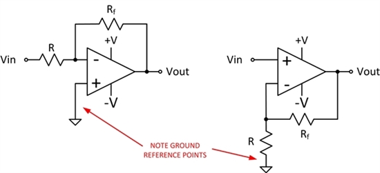
Since many designs of classic circuits used split supplies, ground was the common point for all signal references (+/- V).  That is, the analog signals would swing around ground.  The basic inverting and non-inverting amplifiers shown in figure 1 both use ground as the reference bias point and must have split supplies.  You may note that if you try to use the inverting topology with V- connected to ground, it will not work.  The output cannot swing below ground to drive the differential input voltage to zero.  So what do you do if you want to use newer, higher performance, lower power operational amplifiers?  Simple… read on.

FIGURE 1 - Classic Op-Amp Configurations (left is inverting, right is non-inverting)

Image may be NSFW.
Clik here to view.

This is a simple trick that will allow you to dive into all the classic designs and convert them to single supply operation.  Each of the classic topologies uses ground as the reference point.  To convert a design to single supply, this point must move to a new bias point that is within the operating range of the amplifier – a midpoint value.  If you are using a +12V and ground, then the center bias point would +6V.  Sounds very simple! Make a voltage divider with two resistors from the supply to ground and replace the ground connections with the new +6V divided value… right?  Maybe hang some capacitance on the output to filter the bias voltage, sounds good. Not so fast…

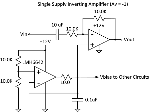
Depending on the topology, significant currents may be flowing in and out of the original ground point.  This means the new single supply system needs an active bias voltage control to regulate the output by both sinking and sourcing current.  A solution to that is shown in Figure 2.  Using a high power, wide bandwidth op-amp such as the LMH6642 (or LMH6644 if you want a quad), the new design will work from a single supply.  The new signal reference is now the output of the bias generator which is halfway between the rails.  Notice the series resistor on the output of the LMH6642.  This is to prevent the internal compensation from being affected which will reduce phase margin and potentially cause high frequency oscillations on the output.  Not something you want to happen for a reference voltage!

Figure 2 - Improved Single Supply System - Inverting Amplifier

Image may be NSFW.
Clik here to view.

Figure 2 shows that the bias circuit will drive other amplifiers (or devices) in your system (based on the drive of the LMH6642).  So if you are building filters, you can utilize the same bias point across the stages.  Hope this simple little trick helps you get over the single supply blues - it has helped me countless times!  Till next time...

Image may be NSFW.
Clik here to view.

Rail-to-Rail Inputs—what you should know!

Rail-to-Rail (R/R) op amps are extremely popular, especially useful with low supply voltage. You should know how R/R inputs are accomplished and understand some trade-offs.

Figure 1 shows a typical dual-input R/R stage comprised of both N and P-channel transistor pairs. The P-channel FETs handle the signal through the lower portion of the common-mode voltage range, to slightly below the negative rail (or single-supply ground). The N-channel FETs operate with common-mode voltage near and slightly above the positive rail. Additional circuitry (not shown) directs traffic, determining which input stage signal is processed by the next stage. Most of our dual input stage op amps are designed so that the transition occurs approximately 1.3V from the positive rail. Above this voltage, there is insufficient gate voltage for the P-channel stage so the signal path is redirected to the N-channel stage.

Image may be NSFW.
Clik here to view.

The P and N input stages will have somewhat different offset voltages. If the common-mode voltage moves through this transition (as it does with R/R G=1 operation), it creates a change in the offset. Some op amps are factory trimmed by laser or electronic trimming, adjusted to reduce the offset of the input stages. This reduces the change through the transition but still leaves a residual bobble. The circuitry controlling the transition from P to N input stage is referenced to the positive supply voltage, not ground. On a 3.3V supply the transition moves to an awkward point—mid-supply.

While unnoticed in most applications, this change in offset voltage may be an issue if high accuracy is required. It can also cause distortion in AC applications. But, again, this will only be seen if the common-mode input voltage crosses the transition between stages.

Figure 2 shows a second type of R/R input stage. An internal charge pump boosts the voltage powering a single P-channel input stage to approximately 2V above the positive supply rail. This allows a single input stage to perform seamlessly over the full rail-to-rail input voltage range—below the bottom rail to above the top rail. No transition glitch.

Image may be NSFW.
Clik here to view.

Charge pump… it sounds spooky to some designers. They’re noisy, right? But our most recent ones are remarkably quiet. Very little current is required because it’s only powering the input stage. There are no extra pins or capacitors—it’s all internal. Charge pump noise is below the broadband noise level; rarely can it be seen in the time domain. Applications that analyze the spectral response below the broadband noise level, however, may see some artifacts.

Not all applications need an op amp with R/R input. Inverting op amp circuits or amplifiers in gain greater than unity, for example, often do not require R/R input, yet still have R/R output. (Maybe this needs another blog.) Do you really need a R/R-input amplifier? Many engineers prefer to use them so they don’t need to worry about exceeding the common-mode range. They use the same op amp in various points in their system—some needing R/R input, others not. Whatever your choice, with knowledge of the R/R types and tradeoffs, you can select more wisely. If in doubt, you are welcome to ask us on our E2E forum.

Here are a few example op amps:

  • OPA340   Two-Input Stage, Trimmed Offset, 5.5MHz R/R CMOS
  • OPA343   Two-Input Stage, Untrimmed Offset, 5.5MHz R/R CMOS
  • OPA320   Charge-pumped Input Stage, Trimmed Offset, 20MHz R/R CMOS
  • OPA322   Charge-pumped Input Stage, Untrimmed, 20MHz R/R CMOS

Thanks for reading and your comments are welcome.

Bruce       email:  thesignal@list.ti.com (Email for direct communications. Comments for all, below.)

   Check out 55+ other interesting technical topicsThe Signal blogs.


Image may be NSFW.
Clik here to view.

TI Sitara Linux is Yocto Project Compatible

The TI Arago distribution for Sitara ARM Processors has been accepted as Yocto Project Compatible. TI is the only ARM silicon vendor with this compatibility. This acceptance shows TI's commitment to streamline Linux development and our involvement in the Yocto Project and Community. This support allows you to:

  • Leverage the well-defined foundational layers of the Yocto Project
  • Access OE-Core file system
  • Effectively tailor software distributions to the requirements of a particular application

For more information around Yocto & TI including training, white paper and a Yocto & TI overview video go to www.ti.com/mainline

To download the latest Sitara Linux SDK based on Yocto go to www.ti.com/sitarasdk

Image may be NSFW.
Clik here to view.


Alejandro Erives, Sitara ARM Processors Brand Manager

Image may be NSFW.
Clik here to view.

IAC or DIY? No, these aren’t stock tips!

IAC is what I call integrated analog circuits, some prefer AFE (analog front ends) while others would say IS (integrated solutions.) Whereas DIY has a universal meaning, “do it yourself!”

So the question now is, are you better off with an IAC over DIY, and why? It depends on the application, expertise, time to market, and total cost.

It’s almost like choosing a watch. Do you want it sporty or classy? Would you like a self winding automatic movement or quartz? How about crystal sapphire or hardened mineral glass? Or do you just want to know what time it is?

Consider an IAC in applications where several platforms could “reuse” the design with a quick spin. This is especially true for applications like temperature control and monitoring, weigh scales, and medical instrumentation, such as ECG/EEG and pulse oximetry. Most IACs are supported by easy-to-use software meant to help the system designer expedite a design and get a very good idea on the capabilities of these devices before deciding to prototype.  Some popular devices include the ADS1298 and ADS1299 for ECG and EEG respectively, the LMP9100 front end for gas monitoring and the AFE4400 complete sub system sub system for pulse oximetry.

Image may be NSFW.
Clik here to view.

On the other hand, there is always the DIY approach because of the 20nV/°C of drift which can only be accomplished by a super high precision op amp, such as the LMP2021. There are those looking for that 1nV which can only be found in a high voltage bipolar amplifier like the OPA211, and those who prefer analog-or digital filtering because that’s their secret sauce.

The choice is yours and you know your needs better than anyone, but the bottom line is more isn’t necessarily always better, if you’re racing the clock trying to put out a new product, then IAC is your best bet. If you’ve got room to spare on your board and want the highest quality product then perhaps a DIY approach is for you.

Let me know if an IAC or a DIY worked better for you. Or, ask questions and share knowledge with fellow engineers on the Support Forums in the TI E2E Community.  

Image may be NSFW.
Clik here to view.

Bluetooth Is for the Internet of Things – My thoughts from Bluetooth World 2013

Last week, the Bluetooth SIG hosted the first Bluetooth World conference in Shanghai, China. Normally reserved for members, the conference opened its doors to non-members who were interested in learning more about Bluetooth technology and trends.

While a portion of the conference was tied to the existing markets for Bluetooth and Bluetooth low energy like health and fitness devices and proximity tags, overwhelmingly the theme of the conference was that this is just the beginning. More traction worldwide. More applications. More devices.

 Where the growth is

At the center of this growth is that Bluetooth and Bluetooth low energy have an important role to play in the Internet of Things (IoT). While it might not seem intuitive at first because Bluetooth does not connect to the Internet, the technology complements the other work horses of the IoT, namely Wi-Fi and ZigBee.

Wi-Fi has established itself for home automation and networking applications and is starting to make inroads in connected cars. Likewise, ZigBee is finding success in smart grid and home automation as well as lighting because of its mesh networking and low power capabilities.

So where does Bluetooth fit? With low power modes and low cost, Bluetooth/Bluetooth low energy can connect the last 10 meters—for advanced remote controls to operate TVs and set-top-boxes, to obtain data from a basketball, pill bottle or other home electronics, portable devices, sporting and medical equipment and share that data with a smartphone or tablet to upload to the Internet.

Image may be NSFW.
Clik here to view.

Sensors, Bluetooth and the IoT

The use of sensors is also expanding the use of Bluetooth in the IoT. Sensors used to determine temperature, movement, humidity, light and more are being paired with Bluetooth/Bluetooth low energy connectivity to gather more information from the billions of devices that have yet to be connected. To this point, TI showed off its Bluetooth low energy SensorTag kit at Bluetooth World in a standing room only training session. The SensorTag is a development tool that can get a sensor-based app up and running in minutes. TI also demonstrated the industry’s only Bluetooth/Bluetooth low energy dual-mode solution – the CC2564– and several customer products during the vendor showcase and one-on-one with the hundreds of attendees at the show.

Image may be NSFW.
Clik here to view.

What the next year will bring

Bluetooth is quickly expanding into new applications, while it is also gaining traction in new regions around the world. Shanghai was a perfect backdrop for the 2013 event since China is embracing Bluetooth connectivity. The number of companies focused on making consumer products for the China market is growing rapidly, as is the demand for technologies that are simple, cheap and already integrated in the smartphones (i.e. Bluetooth low energy) because of the familiarity for consumers.

The possibilities are endless in terms of what Bluetooth can be connected to thanks to its battery friendly, low cost and fairly ease of design compared to other RF technologies. And when added to the Wi-Fi and ZigBee networks at the foundation of the IoT, Bluetooth and Bluetooth low energy become a true extension to connect battery-powered devices. We look forward to the next year of Bluetooth developments and the new and exciting applications that are changing how we live. How are you using Bluetooth technology?

-- Sid

Image may be NSFW.
Clik here to view.

The coolest Chronos applications in existence.

Do you ever think about what other engineers are doing with their Chronos? I found myself wondering just that and scoured the web for the coolest applications out there.


Image may be NSFW.
Clik here to view.


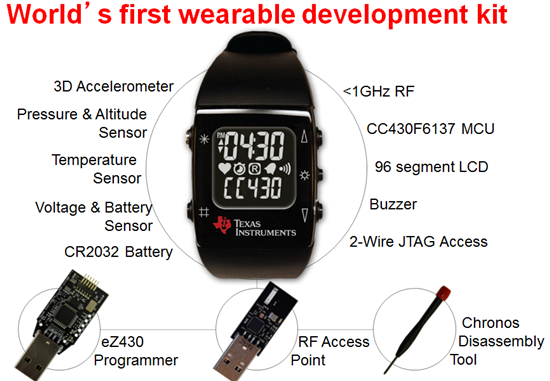
The eZ430-Chronos development tool has been available for quite a while now, but for those of you that don’t know, it is a fully programmable development tool in a watch form factor with a sub-1GHz radio built in. It is about time we showcase the most creative and exciting projects that people have created on such a platform. Let’s get started!

  • The Ultimate Workout Companion

The Chronos is a watch and with that in mind, the health and fitness area is a perfect place to start. This watch can do everything from counting footsteps to measuring heart rate. It can then combine its inputs to determine calories burned! All this with built in functionality to control the workout video you have playing on your TV.


(Please visit the site to view this video)


  • The Wireless Door Lock

I am always happy when someone comes up with a way for me to carry less stuff. The designers of this project eliminated the need for keys to your home. They even thought to add a passcode so the system is truly secure!


(Please visit the site to view this video)

  • The Remote Control

When I was growing up, I never really had a problem using the remote controls that came with my toy cars. Now I do! Who doesn’t want to control a vehicle with nothing but their wrist?


(Please visit the site to view this video)


  • The Flying Mouse

This may go hand and hand with the previous project, but as a video gamer, this one raises the bar in a way I really appreciate. Control your PC by moving your wrist…Why not? I’m not going to lie. If I had this when I was younger, I could have saved a bunch of my allowance by trading my force feedback wheel for that copy of Ender’s Game!


(Please visit the site to view this video)

Wow! There are a lot of people out there doing amazing things with the Chronos. I’m not sure anyone out there can do better. Disagree? Then prove me wrong. If you need a Chronos to get started, go checkout TI Deals and then come back here to share your best Chronos story.

Image may be NSFW.
Clik here to view.

BeagleBoard.org will unleash the beast with the next-gen BeagleBone at DESIGN West 2013


Image may be NSFW.
Clik here to view.
    

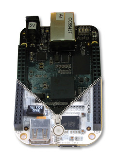
BeagleBoard.org and Sitara ARM processors will let loose the newest Beagle at Design West in San Jose, April 23-25. The next-generation BeagleBone– based on Sitara ARM processors – brings more bark and bite to the family.

Stop by the TI booth (#1607) to dig-up some fun as the next-gen BeagleBone is the brawn and brain of some really cool projects, including a 3D printer, a robotic spider and the BeagleStache cam. Plus, get autographs from the BeagleBoard.org alpha dogs (and co-founders) Jason Kridner and Gerald Coley.

Want to get your paws on the next-gen BeagleBone before everyone else? You’ll have your chance to win one at two Beagle-related events. Which two? I’m not telling.

Beagle Events

Tuesday, April 23Wednesday, April 24Thursday, April 25

Open Source Hardware Panel Discussion
Speaker: Jason Kridner
Expo Theater
12:00 – 12:45 p.m. PDT
Add to schedule

Mouser Meet and Greet
Speaker: Jason Kridner
Mouser booth #1808
noon – 1:00 p.m. PDT
How to Work with Open Source More Effectively
Speaker: Jason Kridner
210 EF
8:30 – 9:15 a.m. PDT
Add to schedule
In-booth training: Meet the next-generation BeagleBone!
Speaker: Adrian Valenzuela, Sitara marketing
TI booth #1607
1:00 – 2:00 p.m. PDT
In-booth training: Meet the next-generation BeagleBone!
Speaker: Adrian Valenzuela, Sitara marketing
TI booth
1:00 – 2:00 p.m. PDT
Beagles and Boards, and Raspberry Pi, Oh my!
Speaker: Jason Kridner
Expo Theater
1:00 – 1:45 p.m. PDT
Add to schedule
Element 14 Meet and Greet
Speaker: Jason Kridner
Element 14 booth #2340
1:15 – 2:00 p.m. PDT

Rapid Prototyping with Sensor/Actuator Breakout Boards using Bonescript
Speaker: Jason Kridner 
Hands-On Lab: Booth 2144 
2:00 – 2:45 p.m. PDT
Add to schedule

Beagles and Boards, and Raspberry Pi, Oh my!
Speaker: Jason Kridner
Expo Theater
2:00 - 2:45 p.m. PDT
Add to schedule

Beagles and Boards, and Raspberry Pi, Oh my!
Speaker: Carlos Betancourt, Sitara marketing
Expo Theater
3:00 – 3:45 p.m. PDT
Add to schedule
MCU Hacks: Russian Nixie Tube Clock Design & Mustache Camera
Speaker: Jason Kridner
210 GH
3:15 – 4:00 p.m. PDT
Add to schedule

Gadget Freak DIY Lab
Speaker: Jason Kridner
Expo Theater
5:00 – 5:45 p.m. PDT
Add to schedule

You’ll scream for ice cream and Beagles: At the Element14 and Mouser meet and greets there will be ice cream AND an opportunity to win the next-gen BeagleBone and other Beagle goodies! (OK. So I did tell you which two events.) We will draw thirty winners after each meet and greet.

Plus, there will be more opportunities to win by showing your puppy love for Beagle onsite and online during Design West. Be on the lookout for more details.

Are you excited to see the next-gen BeagleBone as much as we are? What Beagle events have you howling at the moon? Tell us about it here and be sure to tell your friends, family, colleagues and your pets by clicking on the Twitter, Google + and Facebook like buttons above.

Image may be NSFW.
Clik here to view.


Boris, the Beagle, buried Alejandro Erives (Sitara ARM Processors Brand manager). Here's hoping Boris digs him up soon - at least, before he starts to smell.

Image may be NSFW.
Clik here to view.

TI is charged up about Mophie

You’re ready to update your status or respond to those incoming emails – then your smartphone dies. And you’re without your charger. Running out of cell battery juice at a critical moment has happened even to the most organized – even those Type As.

That’s where the Mophie juice pack comes in. It’s a durable, portable battery-charging case for smartphones that can more than double the battery life of an Apple iPhone or Samsung Galaxy S III Android phone. And TI battery-charging integrated circuits (ICs) are what give the Mophie its battery boImage may be NSFW.
Clik here to view.
ost.

“I remember one time I was driving, and my phone died an hour before my car broke down,” says TI employee accounts specialist Kyle Brown, who is a personal fan of the charger. “If it had not been for the Mophie case that was charging my phone back up, I might have been stuck out in the middle of nowhere for hours.”

How it works

The Mophie juice pack has a rechargeable lithium battery. When you slide your phone into the case, a connector at the base plugs into the micro-USB port at the bottom of your phone. Flip the standby switch on the back from red to green to start charging your phone.

To charge the Mophie juice pack, simply connect it to a USB power source, such as a wall charger, car charger or your computer, with the included micro-USB cable. You can charge the juice pack while it’s on or off your phone. If you charge with the case on, it will also charge your phone.

The juice pack contains TI’s bq24040, which serves as the USB Li-ion battery-charger IC, and also features the bq2425x and bq2419x family of battery-charging ICs, which TI unveiled on March 25. These ICs enable faster, cooler charging for single-cell, Li-Ion battery packs for an array of applications ranging from power banks and packs to 4G LTE routers, Wi-Fi speakers, portable medical and industrial designs. The Mophie juice pack also contains the LM324 operational amplifier.

“The Mophie juice pack gives you very good protection, and puts your mind at ease knowing that your phone will not run out of battery,” Brown says. “They have always done a great job keeping the cases sleek and stylish, ensuring that the phone is secure without adding a lot of bulk or weight."  

For more information on the Mophie case, click here.

Image may be NSFW.
Clik here to view.

Next Gen BeagleBone is coming - sign up for more info!

Hello Educators and Students, the next generation BeagleBone is coming soon.  Are you signed up to receive more info?

Check out this teaser video and sign up to receive info as soon as the product launches www.beagleboard.org/unzipped

(Please visit the site to view this video)

With lower price, Higher performance, On-board HDMI to connect directly to TVs and monitors, More and faster memory now with DDR3 and On-board flash storage frees up the microSD card slot

It promises to be even more compelling for teaching and projects!

Cathy Wicks
TI University Program and beaglefan

www.ti.com/university 

Image may be NSFW.
Clik here to view.

BeagleBoard.org will unleash the beast with the next-gen BeagleBone at DESIGN West 2013


Image may be NSFW.
Clik here to view.
    

BeagleBoard.org and Sitara ARM processors will let loose the newest Beagle at Design West in San Jose, April 23-25. The next-generation BeagleBone– based on Sitara ARM processors – brings more bark and bite to the family.

Stop by the TI booth (#1607) to dig-up some fun as the next-gen BeagleBone is the brawn and brain of some really cool projects, including a 3D printer, a robotic spider and the BeagleStache cam. Plus, get autographs from the BeagleBoard.org alpha dogs (and co-founders) Jason Kridner and Gerald Coley.

Want to get your paws on the next-gen BeagleBone before everyone else? You’ll have your chance to win one at two Beagle-related events. Which two? I’m not telling.

Beagle Events

Tuesday, April 23Wednesday, April 24Thursday, April 25

Open Source Hardware Panel Discussion
Speaker: Jason Kridner
Expo Theater
12:00 – 12:45 p.m. PDT
Add to schedule

Mouser Meet and Greet
Speaker: Jason Kridner
Mouser booth #1808
noon – 1:00 p.m. PDT
How to Work with Open Source More Effectively
Speaker: Jason Kridner
210 EF
8:30 – 9:15 a.m. PDT
Add to schedule
In-booth training: Meet the next-generation BeagleBone!
Speaker: Adrian Valenzuela, Sitara marketing
TI booth #1607
1:00 – 2:00 p.m. PDT
In-booth training: Meet the next-generation BeagleBone!
Speaker: Adrian Valenzuela, Sitara marketing
TI booth
1:00 – 2:00 p.m. PDT
Beagles and Boards, and Raspberry Pi, Oh my!
Speaker: Jason Kridner
Expo Theater
1:00 – 1:45 p.m. PDT
Add to schedule
Element 14 Meet and Greet
Speaker: Jason Kridner
Element 14 booth #2340
1:15 – 2:00 p.m. PDT

Rapid Prototyping with Sensor/Actuator Breakout Boards using Bonescript
Speaker: Jason Kridner 
Hands-On Lab: Booth 2144 
2:00 – 2:45 p.m. PDT
Add to schedule

Beagles and Boards, and Raspberry Pi, Oh my!
Speaker: Jason Kridner
Expo Theater
2:00 - 2:45 p.m. PDT
Add to schedule

Beagles and Boards, and Raspberry Pi, Oh my!
Speaker: Carlos Betancourt, Sitara marketing
Expo Theater
3:00 – 3:45 p.m. PDT
Add to schedule
MCU Hacks: Russian Nixie Tube Clock Design & Mustache Camera
Speaker: Jason Kridner
210 GH
3:15 – 4:00 p.m. PDT
Add to schedule

Gadget Freak DIY Lab
Speaker: Jason Kridner
Expo Theater
5:00 – 5:45 p.m. PDT
Add to schedule

You’ll scream for ice cream and Beagles: At the Element14 and Mouser meet and greets there will be ice cream AND an opportunity to win the next-gen BeagleBone and other Beagle goodies! (OK. So I did tell you which two events.) We will draw thirty winners after each meet and greet.

Plus, there will be more opportunities to win by showing your puppy love for Beagle onsite and online during Design West. Be on the lookout for more details.

Are you excited to see the next-gen BeagleBone as much as we are? What Beagle events have you howling at the moon? Tell us about it here and be sure to tell your friends, family, colleagues and your pets by clicking on the Twitter, Google + and Facebook like buttons above.

Image may be NSFW.
Clik here to view.


Boris, the Beagle, buried Alejandro Erives (Sitara ARM Processors Brand manager). Here's hoping Boris digs him up soon - at least, before he starts to smell.

Image may be NSFW.
Clik here to view.

TI hosts talk with academy founder who is making STEM resources available to all

TI recently hosted a conversation about science, technology, engineering and math (STEM) education with Salman Khan, founder and executive director of the Khan Academy. Khan, who shared his perspective on the future of education, was joined by representatives of the Dallas Regional Chamber, EducateTexas and Austin College.

Image may be NSFW.
Clik here to view.
Khan Academy is a nonprofit organization with the goal of changing education for the better by "providing a free, world-class education for anyone, anywhere." The educational resources provided on the academy's website are available to anyone for free. The site hosts more than 4,000 kindergarten-through-12th-grade education videos covering topics from biology, chemistry and physics to the humanities and art.

Read the full story on the Corporate Citizenship news site.

Image may be NSFW.
Clik here to view.

Embedded Android Boot Camp

Android embedded development can be both exciting and a bit daunting. To help you with your development, Barr Group has created the hands-on Embedded Android Boot Camp™. It's a one-week immersion into utilizing Android on the Sitara ARM Processors AM335x Starter Kit (TMDSSK3358), consisting of a series of lectures and hands-on exercises. This intense educational (and exciting!) program is designed to lead software engineers through the steps of bringing up embedded hardware with Android, developing custom Android device drivers, and exposing custom hardware functionality in Android apps.

What You'll Learn

Everyone who attends the Embedded Android Boot Camp will learn:

  • How to modify bootloaders for embedded hardware
  • How to modify and build the Linux kernel
  • How to create and debug Linux device drivers
  • How to customize and build the Android software stack
  • More than 50 practical tips for simplifying and speeding Android ports
  • How to avoid common Android development pitfalls
  • and so much more!
Image may be NSFW.
Clik here to view.

The first session is in Maryland from April 29th to May 3rd with other locations announced soon. For more information and to register go to the Embedded Android Boot Camp training page.


Alejandro Erives, Sitara ARM Processors Brand Manager, puts on his Android boots one leg at a time.

Image may be NSFW.
Clik here to view.

Applications and benefits of using an integrated LCD

Last week, I wrote about our vast portfolio of MSP430 devices with integrated LCD and memory of up to 512kB Flash.  Now let’s get down to the nitty gritty and talk about some applications where this technology is beneficial.

There is a display on almost anything these days.  You can see displays around your home on things such as thermostats, appliances and automatic light switches.  If you’re anything like me, you  probably hit the snooze button several times each morning on your alarm clock after viewing a display that tells you it’s WAY too early to wake up.  You might also wear a display on one of those trendy new fitness watches that monitor your daily activity.  A health condition could also require you to view a display every few hours when reading blood sugar levels in monitoring devices.  You can also monitor your electricity usage via a meter on your house that also has a display.  The possibilities are endless! 

The MSP430 portfolio with LCD integrated allows easy coding to control several glass displays in different solutions.  The LCD controller supports up to 8-mux glass displays.  For example, you can control a small 7-segment display for a clock number.  Or a large 320-segment display to support Asian characters or black and white graphics.  You can use one MSP430 microcontroller to control two small displays.  If needed, it’s easy to use two MSP430s to control greater than 320-segment displays.   If you’re looking for a quick way to get started coding with some low level commands for the LCD, I would recommend checking out the F471xx and the F67xx series.  Whichever solution is best for your product, MSP430 has the right microcontroller for you.

The last, but most important, factor to keep in mind is the low power aspects of the integrated LCD.  Once the LCD controller is setup, it will continue to run without the use of the CPU.  This means that for all those portable applications running on a battery, the display is not consuming all the power.  Think how critical this is for diabetes patients who need to regularly monitor their blood sugar level!  Running to the nearest store to buy batteries every week is not an option.  Therefore, running your application in the lowest power mode, but keeping the LCD active is very important!

Check out this video about one of our many feature-rich devices with integrated LCD for large segment displays. 

Image may be NSFW.
Clik here to view.

Stay tuned next week when we wrap up this LCD blog series and talk about development tools to get you started. 

Image may be NSFW.
Clik here to view.

TIer Don Shaver is a tireless advocate for Power Line Communications standardization. For that, he just nabbed an IEEE award.

“You are the recipient of the IEEE ComSoc Technical Committee on Power Line Communications 2013 TC-PLC Inter-disciplinary Research and Application Award,” the email read. The recipient: TIer Don Shaver, who is so humble, he nearly deleted the email before reading it – he was pleasantly surprised when he discovered it was for him.

Image may be NSFW.
Clik here to view.
Shaver is a TI Fellow and 36-year veteran who has held multiple roles within the company, including directing new technology business and international standards. He has developed systems, software and application-specific processors in defense, geophysical and communications applications, and established two TI semiconductor research and development laboratories.

He’s also the director of industrial relations in the 10-member Institute of Electrical and Electronics Engineers (IEEE) TC-PLC Technical Committee, which spans all areas of communications over power lines, including smart metering, automotive applications and in-home energy management. The committee’s goal: to monitor the analytical, theoretical, simulation, experimental and practical aspects of digital communications over power lines. And, to help set design and standard guidelines.

The committee also works to organize events, sponsor conferences, and promote the development of standards through papers and workshops. Basically, it’s an essential job that requires time devoted to helping drive PLC-related developments in the IEEE (of which Shaver is a senior member). It’s extra time that Shaver commits.

It ties to his current role as a chief architect for TI’s Smart Grid business unit. Shaver is always looking for next-generation technology, and works to find ways to improve products and pinpoint areas where TI can differentiate and innovate -- and not just in power line communications.

Shaver has devoted time to international standards activities and alliances for more than two decades, and is expected to reach completion of setting key narrowband PLC standards this year. “If you don’t have standards, your technology is not going to be successful in the market,” he says.

On the side, he also represents TI’s Smart Grid solutions across additional organizations like the International Telecommunications Union, and drives TI’s influence on governmental standards and regulatory activities. He has also been awarded 16 patents.

It’s a long list of accomplishments. Yet despite this, and the award, Shaver remains modest. “The award was quite a pleasant surprise, because you don’t actually strive for this kind of recognition,” he says. “The goal is to make contributions to the technical and industrial community in order to help align TI with the industry. But it’s also like a pat on the back – it motives me to continue doing this.”

Image may be NSFW.
Clik here to view.

Imagine the impact…TI’s KeyStone SoC + HP Moonshot

Last week, market leader Hewlett Packard announced a huge change in the server landscape with its recent Moonshot announcement. HP responded to the new challenges being driven by the diverse requirements of mobility, cloud, social and Big Data by enabling application-optimized servers rather than the traditional, one-size-fits-all servers. TI is very excited to be part of such a monumental industry shift as we strongly believe that a better way to cloud is driven by such purpose-driven server architectures.

TI’s participation in HP’s Pathfinder Innovation Ecosystem is the first step towards arming HP’s customers with optimized server systems that are ideally suited for workloads such as oil and gas exploration, Cloud Radio Access Networks (C-RAN), voice over LTE and video transcoding. This collaboration between TI and HP is a bold step forward, enabling flexible, optimized servers to bring differentiated technologies, such as TI’s DSPs, to a broader set of application providers. TI’s KeyStone II-based SoCs, which integrate fixed- and floating- point DSP cores with multiple ARM® Cortex™A-15 MPCore processors, packet and security processing, and high speed interconnect, give customers the performance, scalability and programmability needed to build software-defined servers. HP’s Moonshot system integrates storage, networking and compute cards with a flexible interconnect, allowing customers to choose the optimized ratio enabling the industry’s first software-defined server platform. Bringing TI’s KeyStone II-based SoCs into HP’s Moonshot system opens up several tantalizing possibilities for the future. Let’s look at a few examples:

Think about the number of voice conversations happening over mobile devices every day. These conversations are independent of each other, and each will need transcoding from one voice format to another as voice travels from one mobile device, through the network infrastructure and to the other mobile device. The sheer number of such conversations demand that the servers used for voice transcoding be optimized for this function. Voice is just one example. Now think about video and music, and you can imagine the vast amount of processing required. Using TI’s KeyStone II-based SoCs with DSP technology provides optimized server architecture for these applications because our SoCs are specifically tuned for signal processing workloads.

Another example can be with C-RAN. We have seen a huge push for mobile operators to move most of the mobile radio processing to the data center. There are several approaches to achieve this goal, and each has pros and cons associated with them. But one thing is certain - each approach has to do wireless symbol processing to achieve optimum 3G or 4G communications with smart mobile devices. TI’s KeyStone II-based SoCs are leading the wireless communication infrastructure market and combine key accelerators such as BCP (Bit Rate Co-Processor), VCP (Viturbi Co-Processor) and others to enable 3G/4G standards compliant for wireless processing. These key accelerators offload standard-based wireless processing from the ARM and/or DSP cores, freeing the cores for value-added processing. The combination of ARM/DSP with these accelerators provides an optimum SoC for 3G/4G wireless processing. By combining TI’s KeyStone II-based SoC with HP’s Moonshot system, operators and network equipment providers can now build customized servers for C-RAN to achieve higher performance systems at lower cost and ultimately provide better experiences to their customers.

We are very excited to be part of HP’s Pathfinder Innovation Ecosystem because the collaboration between TI and HP engineers are opening a new world of possibilities for so many different markets. Stay tuned for more examples of the impact that TI’s KeyStone II-based SoC with HP Moonshot will create.

For more information about HP Project Moonshot, visit http://www.hp.com/go/moonshot/

Image may be NSFW.
Clik here to view.

Commandments of RS-485

At TI, we often get questions about whether there are any quick tips or tricks to keep in mind when designing with RS-485. So, we've put together a comprehensive list of the top commandments to remember when working with RS-485. If you have any further questions on this topic, our team is always hanging out on our E2E forum, and we would be happy to help. So, without further adieu...

The 14 commandments of RS-485

Image may be NSFW.
Clik here to view.
rs-485 designs

And how to apply them...

1) Use twisted pair cable with Zo = 120Ω or 100Ω

2) Connect bus nodes via daisy chain

3) Terminate unused conductors with RT = Z0 to their local grounds

4) Terminate one cable end with RT1 = Z0

5) Apply failsafe biasing to the other end Image may be NSFW.
Clik here to view.
Image may be NSFW.
Clik here to view.

6) Terminate this end Image may be NSFW.
Clik here to view.

7) Determine maximum cable length with chart bottom right

8) Make stub length no longer than Image may be NSFW.
Clik here to view.
Image may be NSFW.
Clik here to view.

9) You can operate 3V and 5V devices on the same bus

10) For ESD, EFT, and surge protection use SM712

11) Limit clamping current into the transceiver with 10-Ω pulse-proof or MELF resistors

12) Filter signal noise between transceiver and UART with R-C low-pass filters (fc ≥ 5 x DR)

13) For ± 7V GPDs use standard transceivers

       For ± 20V GPDs use SN65HVD17xx

       For higher GPDs use isolated transceivers 

14) Ask questions on TI's E2E Industrial Interface Forum.


Do you have your own tips? Share them with our readers below.

Image may be NSFW.
Clik here to view.

Testing power supply: Measuring Noise

Last week, I posted part 1 of a 3 part series on how to test your power supply design: Testing power supply: measuring efficiency.  I covered the fundamentals about testing, including the necessary equipment and how to prepare a circuit for testing. I also covered how to accurately measure start-up time, current limit, and power supply efficiency. 

Today, I'll touch on another important metric when it comes to testing power supply performance: measuring noise.

What causes power supply noise?

Power supply noise is generated from many different sources. Like any amplifier, power supplies generate many different types of noise, but a switch mode design also has to deal with the noise generated by the inherent switching noise which takes place. A switching power supply can be designed to minimize its switching noise and can include output filters to reduce the noise, but it's impossible to know exactly what levels of noise a power supply will produce until it's actually measured.

Image may be NSFW.
Clik here to view.

Transient Ripple Noise

Why should one measure noise?

The bias voltages within any system are what I like to think of as the foundation of the electrical circuits.  All of the system connects to these sources of power and must deal with its associated noise.  If the noise generated (or passed) from the power supply is beyond what a circuit can tolerate, a system will naturally malfunction.  The issue with noise is that it might be such that it doesn't cause catastrophic failure, at least not all the time. Noise sometimes causes intermittent errors which might not be evident during a thorough system test in a specific environment with a typical set of component values, but might later cause problems.  In some cases, I see software patches written to “cover-up” occasional system errors which may be found to root themselves back to power supply noise. Is software the right way to fix a problem which could have been addressed within the power supply?  I think not, but I best not digress into what might be a somewhat philosophical discussion, better I add that to the list of discussions for later, “Fixing Problems, Software vs Hardware”… 

I occasionally see noisy power supply designs causing a system to fail EMI testing, slowing down a product release.  These slowdowns may be avoided if proper testing was performed and noise issues dealt with earlier in the process.  When it comes to biasing an analog circuit,  power supply noise can result in a lower performance system, possibly reducing the products value to the end customer. Think about the power supply for an analog signal path from a sensor of some sort.  In these systems noise directly impacts the sensitivity of the system, a higher noise floor results in lower sensitivity. When a designer takes the time to actually measure and analyze the noise generated by a power supply they can either accept the performance or almost always make modifications to avoid later system level problems, often at almost no extra cost.  The cost to test and possibly modify a power supply is usually far less then later system level debug and modifications, or the unfortunate situation when a product is released with sub-par performance. 

It’s this attention to detail that makes the difference between a marginally working product, and a highest performance, highest reliability product.

Read in more detail how to measure noise in a power supply in my full article on EDN.

Walk through how to measure noise in your power supply with me in this Engineer It video.

Image may be NSFW.
Clik here to view.

Part 3 on how to measure stability, coming soon.

If you have any questions or comments on how to measure noise, please leave them in the comment section below.

Happy testing!

Image may be NSFW.
Clik here to view.
Viewing all 4543 articles
Browse latest View live