Quantcast
Channel: TI E2E support forums
Viewing all 4543 articles
Browse latest View live

How to design for precision RTD measurements with ADCs

$
0
0

In theory, temperature measurements using resistance temperature detectors (RTDs) should be simple: measure a temperature with an RTD that changes resistance with temperature, measure the resistance of the RTD, and convert that resistance to temperature through an equation or look-up table. What could possibly go wrong?

Many design considerations come into play. You need to select the correct RTD wiring configuration to limit the errors from lead resistance in your application and use the correct circuit topology to measure the RTD; you will need current analog-to-digital converter (IDAC) excitation current sources to drive the RTD. You’ll also need a precision analog-to-digital converter (ADC) with additional features to measure the whole thing. For example, if a standard PT100 RTD is changing roughly 0.4Ω/°C, you’ll need accuracy and precision to get measurements in the 0.1°C range.

TI can help you design your RTD circuit with precision ADCs. You can achieve the accuracy you need by selecting the right measurement method and reducing errors in the measurement.

The application note, “A Basic Guide to RTD Measurements,” gives an overview of RTDs with a discussion on important parameters, tolerance, configurations and basic measurements using ADCs. This document also gives several circuit topologies to help you decide which RTD wiring configuration to use, and the advantages and disadvantages of each. It explains the process of setting up a precision RTD measurement, identifying and reducing measurement errors, and converting the measurement to a temperature.

TI offers several cookbook circuits that provide more in-depth information about different RTD configurations. There are step-by-step design notes with calculations, ADC configuration settings and pseudo-code to help you design your system and get it up and running. These circuits can help you avoid errors in measurements and guide you toward a solution.

Table 1 lists the RTD cookbook circuits available for downloading.

RTD circuit topology

Advantages

Disadvantages

Two-wire RTD, low-side reference

Lowest system-level cost

Least accurate, no lead-resistance cancellation

Three-wire RTD, low-side reference, two IDAC sources

Allows for lead-resistance cancellation

Sensitive to IDAC current mismatch; swapping IDAC currents and averaging two measurements removes the mismatch

Three-wire RTD, low-side reference, one IDAC current source

Allows for lead-resistance cancellation

Requires two measurements, first for RTD measurement, second for lead-resistance cancellation

Three-wire RTD, high-side reference, two IDAC current sources

Allows for lead-resistance cancellation; less sensitive to IDAC mismatch than using a low-side reference

Requires extra resistor for biasing; added voltage may not be compatible with low supply operation

Four-wire RTD, low-side reference

Most accurate, no lead-resistance error

Most expensive

Table 1: RTD circuit topology comparison

A typical RTD measurement system requires a precision ADC, current excitation sources, a precision reference resistance and some lower-cost filter components. The precision ADC often includes internal current references, so the main expense is the reference resistance and data converter.

The next time you need to design a precision RTD measurement system, start with “A Basic Guide to RTD Measurements” and download the cookbook circuits that we have available. You’ll be able to put your system together and make precision temperature measurements with TI’s ADCs.


Going crystal-less is easy with the world's first crystal-less, wireless SimpleLink™ MCU

$
0
0
  Innovation in the semiconductor industry is often about adding on to an existing product, but less is more when it comes to design. At TI, we looked at the electronic build of materials (BOM) surrounding our SimpleLinkTM wireless MCUs and dec...(read more)

Can your RS-485 communication survive the great outdoors?

$
0
0

RS-485 transceivers are designed to withstand harsh environments. In addition to noisy factories, this means RS-485 transceivers must also be robust enough to operate outdoors where communication can be affected by voltage surge events, such as lightning strikes.

So, how do you test if your RS-485 communication is capable of surviving a high-voltage event without waiting outside for a perfectly placed lightning strike?

The International Electrotechnical Commission has established the IEC 61000-4-5 surge immunity standard to help engineers determine a system's level of surge protection. The IEC 61000-4-5 standard is critical for applications with outdoor communications, such as remote radio units, air conditioning units and Internet Protocol (IP) surveillance cameras.

Understanding this standard is essential to ensuring that your systems can withstand anything nature may throw your way. This article will focus on the IEC 61000-4-5 standard as well as different ways to protect your system from outdoor surge elements. We will also show you how to optimize your designs to save space and reduce the number of components.

 What is the IEC 61000-4-5 surge immunity standard?

The IEC 61000-4-5 surge standard is one of the most demanding tests performed on an RS-485 transceiver; the test models a lightning strike or industrial surge. Figure 1 compares three of the commonly required tests for RS-485. The 0.5-kV surge (the red trace) is magnitudes longer in duration and higher in energy (due to low source impedance) than the 4-kV electrical fast transient (EFT) (the purple trace) and 10-kV electrostatic discharge (ESD) (blue trace) tests.

 Surge test compared to EFT and ESD tests

Figure 1: A surge test compared to EFT and ESD tests 

Surge is a common and mandatory requirement for systems exposed to outdoor elements. IEC surge tests simulate the inrush of current into a transceiver, and there are different levels of IEC standard classification criteria (outlined in Table 1). System-level designs commonly have to meet Class 2 (a 1-kV test) or Class 3 (a 2-kV test).

Class

Test level

Maximum peak current (at 2 Ω)

0

25 V

12.5 A

1

500 V

250 A

2

1 kV

500 A

3

2 kV

1,000 A

4

4 kV

2,000 A

Table 1: IEC 61000-4-5 surge classes

There are two ways to protect against surge events:

  1. Design a complex discrete solution using an RS-485 transceiver and several external protection components
  2. Implement a surge-integrated RS-485 transceiver

Let’s first take a look at what the discrete approach requires, and then we can take a look at how TI’s latest RS-485 transceivers, the THVD1429 (and lower-speed option THVD1419), can help simplify the solution.

A discrete surge implementation

Protection devices such as transient voltage suppression (TVS) diodes, metal-oxide varistors (MOVs) and gas discharge tubes are often implemented externally to the transceiver in order to limit the voltage and absorb the surge current. Figure 2 shows the IEC ESD, EFT and Surge Protected RS-485 Reference Design with a standard SN65HVD3082E RS-485 transceiver and the additional external components required to provide surge protection.

Discrete solution with up to seven additional components to surge-protect an RS-485 transceiver

Figure 2: Discrete solution with up to seven additional components to surge-protect an RS-485 transceiver

The first challenge with this approach is that it requires designing with additional components. The second challenge is that very few of these protection devices can comply with the surge standard - meaning that component selection can become very challenging and expensive.

The setup in Figure 2 can achieve surge protection by having the MOVs (Nos. 6 and 7 in the figure) divert current to ground. The transient blocking units (TBUs) (Nos. 4 and 5 in the figure) limit the current going into the transceiver. Any current that passes through these first two stages is then further limited by the TVS diode (No. 3 in the figure) and current-limiting resistors (R) (Nos. 1 and 2 in the figure). These four levels of protection, as indicated in Figure 2, require adding up to seven additional components to the board. This can lead to even more challenges, such as added complexity in design and component selection, the need for larger board space and additional components in the bill of materials.

Reduce design complexity by integrating surge

Rather than implementing a complex, costly and space-consuming design with multiple external protection components, the THVD1429 can help to simplify your system. The THVD1429 is a robust RS-485 transceiver that has integrated TVS protection to withstand 2.5 kV of surge. This transceiver is rated to exceed Class 3 (2 kV) of IEC 61000-4-5 without external protection components.

Take a look at the system-level design of the RS-485 communication in Figure 3, this time using an integrated solution instead of the discrete approach shown in Figure 2. Not only does this solution reduce several external protection components, but the industry-standard eight-pin small-outline integrated circuit (SOIC-8) package of the THVD1429 enables a quick and easy way to evaluate and upgrade existing transceivers.

Figure 3: Integrated solution with the THVD1429 or THVD1419 (2.5-kV surge protection)

In addition to 2.5 kV of integrated surge protection, this RS-485 transceiver family offers several other common types of protection, including 8 kV of contact discharge ESD (IEC 61000-4-2), 4 kV of EFT (IEC 61000-4-4), and 16 kV of human body model ESD. The on-chip protection implementation of these transceivers significantly increases the robustness of the device and end equipment.

Additional resources

Minimize the impact of the MLCC shortage on your power application

$
0
0

There is a growing shortage of multilayer ceramic capacitors (MLCCs), and the situation is likely to persist through 2020. MLCCs are used in almost every type of electronic equipment, due to their reliability and small footprint.

While MLCC manufacturers are taking action to increase their production capacity, demand is still expected to outpace supply, resulting in supply-chain shortages and increased prices for these components.

As a power application designer, you might be wondering about how to minimize MLCC supply risks while the supply chain adapts. In this blog post, I’ll discuss several options to power a typical industrial application rail, and show how selecting the right DC/DC converter can help minimize the impact of the MLCC shortage on the production of your product.

Let’s assume that you’re looking to convert a typical 12-V input voltage into a 3.3-V regulated output, able to deliver 3 A of current. With these parameters, TI’s buck converters quick search will propose several DC/DC converter alternatives for you to choose from for an industrial application. Appropriate solutions will offer excellent thermal performance in a compact quad flat no-lead (QFN) package and efficiencies close to or even above the 90% mark at those conditions. However, specifically looking at the required MLCC count for proper operation, there will be important differences that you will have to consider.

Let’s break down a typical externally compensated peak-current-control topology solution. You’ll need a small (0.1 µF) bootstrap capacitor to provide the gate voltage for the high-side metal-oxide semiconductor field-effect transistor, up to four capacitors (two 10 µF and two 0.1 µF) at the input, and a bigger (100 µF) capacitor at the output. A soft-start capacitor to control the output voltage startup ramp could be necessary, as well as two compensation capacitors for the frequency compensation network. This brings the total MLCC count up to nine for a typical circuit.

Another proposal is the TPS62136, a 3-V to 17-V input, 4-A step-down converter with the DCS-Control topology in a tiny 3-mm by 2-mm QFN package. The higher operating bandwidth and internal compensation of the TPS62136’s DCS-Control topology will enable you to minimize the output capacitor value and significantly reduce the total MLCC component count. The device’s evaluation module includes two 22-µF output capacitors only. A single 10-µF capacitor will suffice at the input, and no bootstrap or compensation capacitor is required. The use of a soft-start capacitor brings the total MLCC count to only four.

The TPS62136 comes in a package with low thermal resistance and gives efficiency close to the 90% mark for the stated conditions. It requires less than half the number of ceramic capacitors and creates a much smaller total solution size than a typical externally compensated, peak-current-mode control device. Figure 1 compares the number of required MLCCs for the circuit configurations discussed.

             Typical circuit schematics for an externally compensated peak-current-mode control device

Figure 1: Typical circuit schematics for an externally compensated peak-current-mode control device (a); and the TPS62136 (b); the required MLCCs are highlighted in red

If you’re looking to reduce the exposure of your power application to MLCC shortage issues, make sure that the DC/DC converter you select allows you to optimize both total capacitor value and count. Our high-operating-bandwidth DCS-Control topology converter portfolio, including the TPS62136, can help without sacrificing performance.

Next week, my colleague George Lakkas will show you how TI’s D-CAP+™ control mode multiphase controllers, converters and modules, including the TPSM831D31, can help you reduce the MLCC count on your motherboard versus competitive solutions.

No avalanche? No problem! GaN FETs are surge robust

$
0
0

We live in silicon-dominated world that shapes our thinking. I find it interesting to imagine an alternate universe where the gallium nitride (GaN) power field-effect transistor (FET) was developed before the silicon FET. Our power converters would certainly have been smaller and more efficient, but more importantly, we’d have been thinking differently.

Take for example the issue of avalanche rating. This parameter relates to the ability of silicon power FETs to survive power-line disturbances caused by lightning strikes or other abnormal occurrences.

The ability to survive a power-line surge is important for any power device. There is concern about the surge-robustness of present-day GaN FETs due to their lack of an avalanche rating. Many of us know Albert Einstein’s quote, “We cannot solve our problems with the same thinking we used when we created them,” and I believe this is good advice. The use of avalanche ratings for surge robustness arose because silicon power FETs do not typically possess much voltage headroom above their maximum voltage rating. When a power-line surge hits, the FET starts breaking down by impact-ionization phenomena, or “avalanche breakdown.” Over the years, the industry engineered the FETs to do this robustly, and the avalanching property has become associated with power-line surge protection. If silicon FETs had been able to switch through surge events, then the thinking would have been different. So let’s rethink surge robustness in a GaN-powered world.

A technical paper at the 2019 IEEE International Reliability Physics Symposium (IRPS) describes the validation of the TI LMG3410R070’s surge robustness. GaN’s superior transient overvoltage capability enables GaN FETs to switch through surge events without avalanching and provides an additional design parameter: a transient surge-voltage rating, VDS(SURGE), which is the peak bus voltage that the FETs can withstand during active operation. A good value was determined to be 720 V, both from customer feedback and through system-level simulation.

Figure 1 illustrates the VDS(SURGE) definition, in coordination with the VDS(TR) parameter already in use on some data sheets. Using these parameters, you can easily limit the peak bus voltage at the device to 720 V during a surge event, as demonstrated in the IRPS paper.

 Figure 1: The surge rating parameter, VDS(SURGE), is the peak bus FET withstand voltage during operation when a surge strikes. Some GaN data sheets already have an off-state transient overvoltage parameter, VDS(TR), that serves to provide additional margin for ringing.
 

Figure 2 shows the switching of the LMG3410R070 through a surge strike, with the validation circuit in the inset. The circuit is powering a 1-kW load under regular operating conditions. The surge generator provides an International Electrotechnical Commission (IEC) 61000-4-5 industry-standard surge waveform, and is set so that the bus voltage at the GaN FETs surges to a peak of 720 V. The input and switched-node waveforms are overlaid to show the GaN FETs actively switching through the strike; switching at 720 V. The test consisted of 50 such strikes per the Verband der Elektrotechnik (VDE) 0884-11 standard while actively powering the load. There was no loss of efficiency, and neither the high- nor low-side GaN FET showed hard failure, demonstrating that they are surge-robust in power supplies.

Figure 2: Demonstration of the surge robustness of the LMG3410R070. The input bus voltage surges from the operating point of 400 V to the target specification of 720 V when the active circuit (inset) is struck with a surge waveform conforming to the IEC 61000-4-5 standard. The switched-node waveform is overlaid on the input waveform to show that the GaN FETs successfully switch through a 720-V peak bus voltage surge.

At TI, we take all aspects of GaN reliability seriously. TI has leveraged its many decades of silicon technology development – while recognizing the new opportunities that GaN brings – to think differently on how to deliver a robust and reliable power solution. Hard-switching the GaN FET in the early stages of technology development is critical, as described in the white paper, “A comprehensive methodology to qualify the reliability of GaN products.” Our recognition of the need for the industry to collaborate, as explored in the blog, “Let’s GaN together, reliably,” led us to help form the Joint Electron Device Engineering Council JC70 committee on wide-bandgap semiconductors. We have invested 20 million device hours in the reliability testing of GaN, including surge robustness.

I would love to imagine how the industry would react to a newly invented silicon power MOSFET in a GaN universe: “A silicon power MOSFET does not switch through surge – it avalanches?

4 Reasons why you should use a boost charger for 2-cell battery application

$
0
0

Finding the perfect battery charger integrated circuit (IC) for your portable electronic device design is not always easy, especially when you need a battery with more than one cell in series (1S) for higher voltages while achieving fast, cool charging in a small board area. In such cases, a boost charger may be what you are looking for. Here are four reasons why you should consider using a boost charger.

1. Boost chargers allow you to take full advantage of 5-V USB’s convenience.

Let’s look at one of the most widely adopted charging inputs in portable electronics – the USB charging port. Remember when every portable device had a different kind of adapter, with barrel-jack charging ports? As USB charging ports became mainstream, it’s now possible for consumers to carry only one adapter and a couple of cables for all of their electronics. USB charging has truly become a way of life.

A 5-V USB adapter and cable (either with a Micro B or a USB Type-C™ port) are cost-effective due to the large number of equipment suppliers; sometimes manufacturers can even exclude adapters from the product box because consumers already own one. A 5-V USB can be designed with up to 15 W of power with USB Type-C, which is enough for most small-size applications.

Using a 5-V USB with a two cells in series (2S) battery is a popular charging combination and a boost charger is required to make this happen. Why? Because it not only takes a 5-V USB input and boosts it up to charge a lithium-ion (Li-ion) battery with 2S, but a high performance boost charger does so in a highly integrated and efficient way, allowing you to get the most out of your portable device designs.

2.  Get the most out of 2S configurations with a boost charger.

Many battery-powered devices use 1S batteries to keep products simple and cost-effective. However, if the system includes higher-voltage blocks, you will need a boost converter to jack up the 1S battery voltage to power them. With a 2S battery and a higher voltage, you can exclude a boost converter and get a longer battery run time.

Applications in which 2S batteries could help include electronic point-of-sale devices or portable photo printers where systems may need a high-voltage print head. Additionally, wireless smart speakers might need a high voltage to supply dynamic current pulses to audio amplifiers, or a small power tool might use a 2S battery to drive the motor effectively and powerfully. An example of a typical 5-V USB 2S battery boost charging system is shown below in Figure 1.

It is also challenging to operate a Li-ion battery (specifically 1S) at low temperatures, as its internal impedance can increase dramatically. In smart home applications used outdoors, like wireless security cameras and video doorbells, when the temperature approaches 0°C, increased battery internal impedance will cause a significant reduction in the battery’s output voltage. The 2S battery configuration provides more voltage headroom to play with.

Figure 1: A boost charger in a 5-V USB 2S battery system

3. Integration eliminates the need to choose between a simple bill of materials or increased functionality.

The integration of boost charging solutions makes the design process simple, with loaded features in a small size.

Do you want your system to turn on instantly when the user plugs in an adapter, even with a depleted battery? Do you want to extend battery life? If the answer to either of these questions is yes, an integrated power path will help you reach your goals. The power path manages the battery’s field-effect transistor (FET) between the system and the battery. This feature guarantees a minimal system voltage so that the system can start when the battery is low, giving the device an instant-on feature. The power path also reliably cuts off the trickle charge when the battery is full to avoid overcharging, thus protecting the battery and extending its life.

A USB Micro B adapter uses D+ and D- to indicate its power sourcing capability. TI boost chargers integrate D+/D- (or DP/DM) detection and can configure the charger’s input current limit when the adapter plugs in. If the adapter is not a standard USB, advanced algorithms like the Vin Dynamic Power Management (VINDPM) and Input Current Optimization (ICO) will help the device detect the adapter’s maximum current capability.

There are more features you can use to make a great charging system. The USB On-The-Go (OTG) feature powers a peripheral device connected to the USB. In OTG mode, the boost charger operates reversely as a buck converter to provide a 5-V bus voltage to the attached device with a current limit. This function saves a buck converter, an inductor and sometimes a power switch. The internal analog-to-digital converter keeps the system aware of what’s going on around and inside the IC. The integrated AC overvoltage protection FET protects the system from input overvoltage events. Figure 2 illustrates the BQ25883, our new boost charger that integrates the power path, D+/D- detection and OTG, among other special features, into one IC.

Figure 2: BQ25883 boost charger system diagram

4. Select the right boost charger for your unique considerations.

Our new boost charger family, BQ25882, BQ25883, BQ25886, BQ25887, provides several options to meet your application requirements. I2C chargers offer great flexibility by setting and changing the charge profile with software and by providing charging status to the system host. The stand-alone charger enables an easy charging setup with external resistors. The cell-balancing version employs an advanced algorithm to quickly balance the voltage of the two cells while charging within one cycle. This is an important feature for products that have two loose cells or that target a long battery life. You can see all of our boost charger family and each of their unique features in Table 1 below.

DeviceBQ25882BQ25883BQ25886BQ25887
VBUS operating range3.0 to 6.2 V3.9 to 6.2 V4.3 to 6.2 V3.9 to 6.2 V

USB detection

D+/D-D+/D-D+/D-PSEL
Power pathYesYesYesNo
Cell balancingNoNoNoYes
OTGUp to 2 AUp to 2 AUp to 2 ANo OTG
16 bit ADCYesYesNoYes
Control interfaceI2CI2CStandaloneI2C
Status pin/PGSTAT , /PGSTAT , /PGSTAT , /PG
Package2.1x2.1 WCSP-25 4x4 QFN-244x4 QFN-244x4 QFN-24

Table 1: TI boost charger family comparison table

 Conclusion

We understand that each portable device design has unique considerations and we want to make it easy to choose the best charger for your design. These four points express the benefits of using a boost charger with 5-V USBs and 2S batteries. We hope you consider a boost charger in the future for a convenient and high performance product.

Achieving high efficiency and reliability in industrial AC/DC power supplies

$
0
0
Industrial power supplies need to be highly efficient, reliable and flexible over broad operating conditions. One of the first criterions is efficiency. Low thermal dissipation results in higher efficiency, which enables systems to forego the fan and...(read more)

Capacitive touch & host controller functionality all in one package can reduce costs, design time and board space

$
0
0

Industrial designs are evolving faster than ever to deliver sleek and reliable human-machine interfaces (HMI), especially in major appliances and building security systems. Mechanical buttons and knobs are making way for capacitive touch, and TI’s CapTIvate™ capacitive touch sensing microcontrollers (MCU) are leading the way in this user experience revolution.

The new MSP430FR2675 and MSP430FR2676 devices will help scale your designs with capacitive touch while reducing costs, design time and board space. Here’s a quick rundown of the benefits of CapTIvate, particularly these two new devices:

  • Ease of use: Saves time and helps you get to market faster through an expansive suite of tools and resources – start your design in less than 5 minutes.
  • Versatility: Offers design flexibility with full configurability from self- and mutual-capacitance sensors and comprehensive libraries for buttons, sliders, wheels and proximity sensing.

  • Lowest power: Detects touch autonomously without CPU intervention and ensure a long battery life.

  • Robustness and reliability: Avoids false touch detects and achieve superior reliability with IEC- and IPX-certified solutions for conducted noise and moisture tolerance.

Figure 1 – MSP430FR267x MCUs Block Diagram

As you’ll see in Figure 1, the MSP430FR2675 and MSP430FR2676 offer 32KB and 64KB of non-volatile memory, giving you more code space for running your application code or storing/logging data. Higher pin-count packages (including a 32-pin VQFN, a 40-pin LQFP, and 48-pin LQFP) give ample serial communications ports and GPIOs for interfacing with other system components. If you want to interface with analog sensors, the integrated 12-bit ADC has you covered. Why rely on a two-chip host MCU + discrete capacitive touch MCU solution? With these devices, designers can leverage the additional memory, pins, and analog to deliver a single-chip solution, thereby saving BOM cost and board space.

These devices are also certified for extended temperature ranges up to 105C – a key requirement for designers within the Appliances market. Furthermore, several noise-immunity post-processing techniques like multi-frequency scanning and oversampling are automated in the CapTIvate IP, enabling a more robust capacitive touch. With these combinations of features, the MSP430FR2675 and MSP430FR2676 are ready to serve as the main system controller in your application.

Portfolio scalability and ecosystem

Figure 2 – CapTIvate MCU Portfolio

Project requirements can change over time, and features may need to be added or removed on the fly. If you want to future-proof your design, you need an MCU family that scales with your requirements.

With the MSP430FR2633 and the introduction of the MSP430FR2675 and MSP430FR2676, CapTIvate now offers pin-to-pin compatible solutions for 16KB, 32KB, and 64KB MCUs in a 32-pin quad flat no-lead (QFN) package (see Figure 2) so changing requirements no longer means restarting your design from scratch.

Explore how these new devices can revolutionize your HMI by pushing the limits of capacitive touch and serving as your main system MCU. Purchase samples of the MSP430FR2675 and MSP430FR2676 microcontrollers today.

Additional Resources:


Minimize the impact of the MLCC shortage using D-CAP+™ control mode

$
0
0

As my colleague Yann said in an earlier blog, there is a growing shortage of multilayer ceramic capacitors (MLCCs), and the situation is likely to persist through 2020. MLCCs are used in almost every type of electronic equipment, due to their reliability and small footprint.

Manufacturers are now looking to replace ceramic capacitors with polymer or other capacitor types. TI D-CAP+™ control mode multiphase controllers, converters and modules (like the TPSM831D31) can help hardware designers reduce the MLCC count on their motherboard versus competitive solutions.

D-CAP+ control mode is a TI proprietary pulse-width modulation controller and converter control architecture that enables very easy loop compensation and excellent loop stability in the presence of varying conditions such as input voltage and the number of phases.

It is a current-mode constant on-time control that uses a true inductor current-sense implementation rather than the injected or emulated ripple current schemes used in the D-CAP2™ and D-CAP3™ control topologies. The D-CAP+ control mode has fixed on-time in steady state and adaptive on-time during load transient condition (AC response), in which the field-effect transistor switch rapidly adjustsas the input and output voltage change to maintain a constant overall switching frequency.

Since the on-time is regulated, there’s a natural period stretching in discontinuous conduction mode (DCM), producing higher efficiency and smooth control when crossing the continuous conduction mode and DCM boundary. D-CAP+ control mode is extremely easy to compensate and does not require the complex type-3 compensation circuits required in voltage-mode control architectures. For more information on D-CAP+ control mode, see the 2014 Power Supply Design Seminar paper, “Choosing the Right Variable Frequency Bulk Regulator Control Strategy

Because D-CAP+ control mode can respond much faster to a processor/application-specific integrated circuit/field-programmable gate array load transient than a fixed-frequency control architecture, it can meet tight tolerance specifications without the number of MLCCs that you would otherwise need for discharging or charging to provide the required energy to the load.

Figure 1 compares a TI voltage-mode controller vs. a D-CAP+ controller during such a load transient. The TPS53647 D-CAP+ control-mode controller has lower overshoot and undershoot, despite having a lower crossover frequency.

Figure 1: Load transient response comparison between voltage-mode and D-CAP+ controllers

The results are similar when making comparisons to competing multiphase controllers with non-D-CAP+ control. Figure 2 compares a 60-A load step from 180 A to 240 A at a 1-kHz load transient repetition rate. The D-CAP+ controller, again, results in lower overshoot and undershoot. These results were replicated on the same motherboard under the exact same conditions. The TPS53681 D-CAP+ controller can achieve better load transient response and faster output voltage settling.

Figure 2: Load transient response comparison between a competing device and TI’s D-CAP+ controller

As a final example, let’s compare a central processing unit (CPU) vendor’s reference design to our own Vcore design. The thermal design current (TDC) was 116 A, while the maximum current (IMAX) was 395 A.

The test data shows that the D-CAP+ controller enables a faster load transient response, which translates to significant MLCC savings vs. the CPU vendor reference design.

Table 1 summarizes the results. The D-CAP+ control solution still meets the CPU overshoot and undershoot specifications while eliminating 42 MLCCs and >700 µF of output capacitance. The Table 1 comparison is applicable to any D-CAP+ control-mode voltage regulator vs. competing regulators.


Table 1: CPU reference design vs. D-CAP+ solution MLCC count comparison for a 116-A TDC and 395 IMAX design

MLCC shortages are not going away anytime soon. If you want to reduce the MLCC count in your design bill of materials so that you can get new projects to market faster, consider using TI’s D-CAP+ controllers, converters and modules.

Additional resources

Robots get wheels to address new challenges and functions

$
0
0
This post was co-authored with Lali Jayatilleke. With logistics centers multiplying to keep up with the growth of online shopping, so are the numbers of wheeled robots which handle many of the strenuous tasks in those logistics centers. The next challenge...(read more)

Intelligent sensing at the edge enables smarter autonomous robots

$
0
0
In my last blog post , I discussed how TI’s millimeter-wave (mmWave) sensors provide intelligence at the edge for robotic arms in factories. Now, I’d like to discuss how mmWave technology provides intelligence at the edge for autonomous robots...(read more)

Frequently asked questions and answers for RS-485 transceivers

$
0
0

By Kaitlyn Mazzarella and Hao Liu

In need of a refresher on RS-485 transceiver design? This blog post features insights based on frequently asked questions within the TI E2E™ Community and is a helpful resource for anyone looking to learn more about this established communications standard.

For information specific to isolated RS-485 transceivers, check out that FAQ post, “Top 7 questions about isolated RS-485 transceivers.”

1. When do you need termination on your RS-485 bus, and how do you terminate properly?

RS-485 bus termination is useful in many applications, as this implementation helps improve signal integrity and reduces communication issues. “Termination” means to match the characteristic impedance of the cabling to the termination network, enabling the receiver at the end of the bus to see the maximum signal power. An unterminated or improperly terminated bus will introduce a mismatch, creating reflections at the end of the network, which can degrade overall signal integrity.

In situations where the two-way loop time of the network is much greater than the signal bit time, termination is not necessary, as the reflections will lose energy each time they reach the end of the network. But for applications where the bit time is not substantially longer than the cable loop time, termination is crucial in order to minimize reflections.

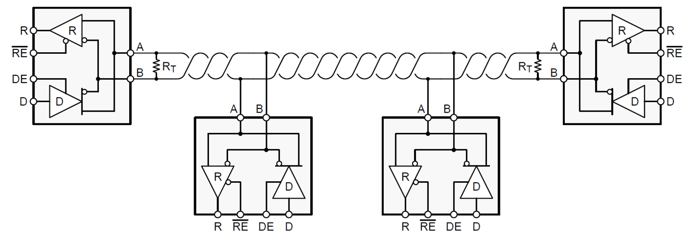
The most basic termination is known as parallel termination and consists of a single resistor, as shown in Figure 1. The RS-485 standard requires 120 Ω as the nominal characteristic impedance, so termination resistors should have RT = 120 Ω as the default value. Read the blog post, “RS-485 basics: When termination is necessary, and how to do it properly.”


Figure 1: RS-485 bus with parallel termination

2. What is fail-safe biasing, and how do you implement it?

Fail-safe biasing is a way for you to ensure that your RS-485 receivers do not fall in an indeterminate state for differential input voltages. The Electronic Industries Alliance (EIA)-485 standard states that the input thresholds of an RS-485 are logic high for differential voltages ≥+200mV and logic low for differential voltages ≤-200mV, which leaves a 400-mV indeterminate state between the high and low thresholds.

You can implement fail-safe biasing in two ways:

  • Select transceivers that have built-in fail-safe input thresholds in the receiver.
  • Add external resistors to create an external bias on the idle bus.

Both methods will ensure a logic-high state on the bus. Read the blog post, “RS-485 basics: two ways to fail-safe bias your network.

3. How do you calculate the maximum number of nodes on an RS-485 bus?

RS-485 is a multipoint differential bus, meaning that all of the nodes on the bus share one common transmission medium. As the total number of nodes increases, the loading on each driver will increase as well.

The Telecommunications Industry Association (TIA)/EIA-485 standard created a hypothetical unit load (UL) to help calculate the maximum number of nodes on a RS-485 bus. The standard states that a driver must be able to drive at least a 1.5-V differential signal across a maximum of 32 unit loads in parallel with two 120-Ω termination resistances at opposite ends of the bus.

Equation 1 expresses the worst-case ratio of the input voltage divided by leakage current to calculate the input resistance. After you’ve established the input resistance of the node, you can calculate the maximum number of nodes on an RS-485 bus with Equation 2:

Input Resistance = Max (VIN/Ileakage)                        (1)


No. of Nodes = 32/Input Resistance                        (2)

 4. How do you know when you need to add a ground wire between nodes?

When designing a remote data link, you must assume that some ground potential differences exist. These voltages add common-mode noise, Vn, to the transmitter output. Even if the total superimposed signal is within the receiver’s input common-mode range, relying on the local earth ground as a reliable path for the return current is unsafe. When the ground potential difference (GPD) exceeds the common-mode range of the receiver (a frequent occurrence with longer cables and high current loads), you will need to use proper grounding techniques.


Figure 2: Remote node configurations: separate grounds (a); directly connected remote grounds (b); separation of device ground and local system grounds (c)

Figure 2a shows remote nodes that are likely to draw their power from different sections of an electrical installation. Any modification to the installation, such as during maintenance work, can increase the GPDs to the extent that the receiver’s input common-mode range is exceeded. Thus, a data link working today might stop operating in the future.

The direct connection of remote grounds through ground wire is also not recommended (Figure 2b), as direct connection causes large ground loop currents to couple into the data lines as common-mode noise.

To enable direct connection of remote grounds, the RS-485 standard recommends the separation of device ground and local system ground via the insertion of resistors (Figure 2c). Although this approach reduces the loop current, the existence of a large ground loop keeps the data link sensitive to noise generated somewhere else along the loop. Thus, a robust data link has not yet been established.

The best approach to tolerate GPDs up to several kilovolts across a robust RS-485 data link and over long distances is to galvanically isolate the signal and supply lines of the bus transceiver from its local signal and supply sources. In this case, supply isolators (such as isolated DC/DC converters) and signal isolators (such as digital capacitive isolators) prevent current flow between remote system grounds and avoid the creation of current loops.

5. What’s the length vs. speed recommendation for RS-485?

The maximum bus length is limited by the transmission line losses and the signal jitter at a given data rate. Because data reliability sharply decreases for jitter of 10% or more of the baud period, Figure 3 shows the cable length vs. data-rate characteristic of a conventional RS-485 cable for a 10% signal jitter.


Figure 3: Cable length vs. data-rate recommendations

On Figure 3, the circle labeled No. 1 represents the area of high data rates over a short cable length. Here, you can neglect the losses of the transmission line; the data rate is mainly determined by the driver’s rise time. Although the standard recommends 10 Mbps, today’s fast interface circuits can operate at data rates as high as 50 Mbps.

The red No. 2 on Figure 3 represents the transition from short to long data lines. You have to take into account the losses of the longer transmission lines. Thus, with increasing cable length, the data rate must be reduced. A rule of thumb states that the product of the line length [m] times the data rate [bps] should be <107.

The red No. 3 represents the lower-frequency range, where the interaction between the cable series resistance and the end-of-line termination results in attenuation of the signal. At a certain point, the amplitude of the signal becomes smaller than what the receiver can properly detect (that is, it does not exceed the VIT threshold).

6. How do you estimate the power dissipation of RS-485?

To calculate the power dissipation, you can divide the power into several parts. When the device powers on with no external load, the power consumption is used for the integrated circuit itself. If you add loads at the output pins, the power of driving the load will be drawn from the device. Since RS-485 has differential signaling, the load is usually added between the A and B pins.

In Figure 4, the blue trace, PDic, is the power the device consumes. For low data rates, the power dissipation mostly comes from the resistive load (the red trace), PDdc. For high data rates, the power dissipation from the capacitive load needs to be accounted for (the green trace), PDac.


Figure 4: Power dissipation sections for calculation

Equation 3 calculates the total power dissipation as:

PDtotal = PDic + PDdc + PDac                      (3)

To calculate the total power dissipation, you must first calculate each portion of the power. The device power consumption is described by Equation 4, where the quiescent supply current, Icc, is specified in the data sheet:

PDic = Vcc*Icc                                    (4)

If you put a resistive load on the bus, the driver generates a voltage (Vod) on it, as illustrated in Equations 5 and 6, where C is the parasitic capacitance, which includes the capacitance of the transceiver, the capacitance of the load and the trace capacitance. The data frequency, f, is also included in the calculation.

PDdc = Vcc*I – I2*R = (Vcc – I*R)*I                           (5)

PDac = 2*2C*f*Vcc*Vod                              (6)

Read the blog post, “How to calculate the power dissipation of high-speed RS-485 transceivers.”

7. How do you protect your RS-485 interface from electrostatic discharge (ESD)?

There are several types of ESD protection, including human body model, International Electrotechnical Commission (IEC) contact discharge and IEC air-gap discharge. If a transceiver has integrated IEC ESD (such as TI’s THVD1450 or THVD1500), then it requires no external components to protect the RS-485 interface from ESD at the level at which the transceiver is specified.

For example, without any external components, the THVD1450 can support 18-kV IEC 61000-4-2 contact discharge. However, many devices in the market do not have this integration, and would require external transient voltage suppression (TVS) diodes. Read the blog post, “How to choose a TVS diode for RS-232, RS-485 and CAN based on voltage ratings.”

8. How do you know if you need an external TVS diode?

Industrial networks must operate reliably in harsh environments. Electrical overstress transients caused by ESD, the switching of inductive loads or a lightning strike will corrupt data transmission and damage bus transceivers – unless you take effective measures to diminish transient impact.

TI devices have been tested according to these standards:

  • The ESD immunity test, IEC 61000-4-2, simulates the electrostatic discharge of an operator directly onto an adjacent electronic component. The THVD1500 and THVD1450 were tested to this standard.
  • The electrical fast transient (EFT) or burst immunity test, IEC 61000-4-4, simulates the everyday switching transients caused by the interruption of inductive loads, relay contact bounce, etc. The THVD1450 and THVD1550 were tested to this standard.
  • Surge immunity test IEC 61000-4-5, the most severe transient immunity test in terms of current and duration, is approximately 1,000 times longer than the ESD and EFT tests. The THVD1429 and THVD1419 were tested to this standard.

TI’s latest RS-485 transceivers from the THVD family integrate various levels of protection according to these standards and do not require additional external protection. The levels of protection are specified in the device’s data sheet.

Anything we missed? Let us know in the comments, and we will send feedback to help you overcome your RS-485 design challenges.

How technology is taking health care beyond the doctor’s office

$
0
0


A doctor treats a patient in a remote village.

On a recent trip to China, Yiannis Papantonopoulos got a glimpse of the future of medicine—and it was inside a suitcase.

The suitcase contained a series of gadgets—including an electrocardiogram (ECG) monitor that can detect anomalies in the heart's electrical signals, a pulse oximeter to detect low blood oxygen sometimes related with heart or lung disease, a blood-glucose monitor to spot abnormal levels of sugar in the blood common with diabetes, an automatic blood pressure monitor and an electronic thermometer.

Thanks to that suitcase, one person can easily hold with one hand the electronic diagnostic equipment needed to provide a clinical-quality medical exam, miniaturized and battery-powered, and ready to be carried into rural areas far from the nearest doctor's office.

"The clinician can run a set of tests on the spot and process the results right there, so they can immediately prescribe any needed treatment," said Yiannis, a manager at our company who specializes in medical device engineering. "A few years ago that would have been absolutely impossible."


 Learn how we’re enabling next-generation healthcare designs

Medicine is undergoing a major transformation in the U.S. and around the world. Much of that change is based around the growing availability of wireless, ever-smaller devices capable of monitoring, imaging and diagnosing patients wherever they happen to be. The results are extending health care beyond the doctor's office and hospital, improving the patient experience while making it more accessible and less costly.

"Physical exams in a clinical setting are still critically important," Yiannis said, "but now we're seeing the capability for health care professionals to continually monitor their patients and extract meaningful information they can act on remotely."

Helping patients at home

Doctor helping patientHealth care based on getting patients to the exam room or hospital bed means care providers have limited visibility into how patients are actually doing in their day-to-day lives.

What's making the difference is the rapid increase in access to a range of highly portable health monitors that can track multiple modalities remotely, such as a miniaturized ECG monitor or pulse oximeter, similar to what you'd see in a clinic.

"Collecting patient information through remote monitoring is creating a real revolution in medicine," said Christopher Almario, a physician and research scientist at Cedars-Sinai in Los Angeles, Calif., who helps direct the hospital's digital-health efforts.

Doctors have begun enlisting wearable or other wireless devices capable of capturing vital signs right in the home on an ongoing basis. By wearing a wrist device the size of a watch that measures heart rhythm, a fully automated blood-pressure monitor or a pulse oximeter, patients avoid the need to stay wired up in a hospital bed, away from family and the other comforts of home. The data can be regularly transmitted to doctors or service providers who can nip a potential health crisis in the bud.

"Being able to track patients' hypertension, blood-sugar level and other data is already having a big impact on how we deal with chronic disease," Dr. Almario said. "We're using remote monitoring to try to predict the risk of cardiac events and other acute conditions."

Shrinking tools that impact lives

It's not just routine health-data monitoring that's extending beyond the hospital and doctor's office. Even some of the most sophisticated imaging and diagnostic tools are becoming available in portable form. As an example, Yiannis points to ultrasound scanners, which have traditionally been cart-mounted in clinics. Now, thanks to component advances that reduce power and size while maintaining signal quality, ultrasound devices are shrinking down to hand-held smart probes that can run on batteries.

Carried by first responders in the field or in ambulances, smart probes can produce sharp, real-time images of internal organs, often revealing details critical to immediate treatment. For patients in remote areas of less-developed countries where fully equipped clinics may be few and far between, a smart probe in the hands of a health worker can mean the difference between a healthy and unhealthy birth, or catching a heart attack before it happens.

"The lack of accurate but affordable diagnostic tools created a real divide in the availability of good health care," Yiannis said. "But now new technology is making the tools accessible everywhere."

 Yiannis Papantonopoulos specializes in medical device engineering.

Better data for better health

If health care outside the hospital continues to advance, medicine will depend on ever-more-capable portable health devices. That's raising the bar increasingly higher on the semiconductor technology behind this equipment.

"Data accuracy and resolution are essential," Yiannis said. "The components need to be capable of detecting fine, nuanced signals in the human body, which is a noisy environment."

At the same time, the size of these devices needs to keep shrinking—along with their power consumption, given that the tools will often have to rely on batteries. That places enormous requirements on the performance of the components.

Meanwhile, health care systems have some of the toughest data-security standards around, which is a real challenge when dealing with vast networks of wireless devices handling patient data outside the clinical environment. The data has to be safeguarded at the highest levels.

But Yiannis insists that engineers are up to the challenge, given what's at stake. "This is technology that touches human lives around the world," he said. "This is a goal that everyone can rally around."

A glitch in your system’s matrix?

$
0
0

“The Matrix” showed a dystopian world where the human race was trapped in a computer simulation. In the movie, the phrase “a glitch in the matrix” described the feeling of déjà vu – experiencing something that doesn’t quite match with what we know about reality.

In electronic systems, signal glitches can and do result in a range of responses, from abnormal behavior to outright failure.

Signal glitches often arise due to the unexpected behavior of circuit implementations used to create a system’s overall signal chain. This unexpected behavior is often the result of a confluence of factors between the integrated circuits (ICs) that make up the signal chain and the various operating modes that the system transitions through in the course of normal operation.

Given the nature of signal glitches, pinpointing their root cause is often difficult, especially for complex systems. Often, the first place that signal glitches occur is during power up, as different subsystems ramp up to their known, stable power-up states. Signal glitches during power up often occur between the output and input pins of circuits within a system or subsystem. The result will be an abnormal boot up and potentially failure during power up.

Designers often turn to complex power-sequencing implementations to stagger the power up of certain subsystems or circuits in order to avoid signal glitches. These implementations often result in longer boot-up times, more complicated software and additional costs.

One simple way to avoid signal glitches during power up is to use building-block ICs that won’t have glitches during power-supply ramp-up. Level-translator devices common in most signal chains enable voltage-level shifting between the input and output pins of devices that reside on two different voltage nodes. Selecting level translators designed to support glitch-free power up can go a long way in preventing signal glitches and avoiding the need for complex power-sequencing schemes.

TI’s latest SN74AXC family of direction-controlled level translators are specifically designed and tested to not have signal glitches, enabling you to avoid complicated power-sequencing schemes that other level translators may require.

One way to test the robustness of a level translator against signal glitches is to perform power-up testing of the device using a combination of different voltage ramp-up rates (volts per second) at different voltage rails supported by the two interfacing devices , VCCA and VCCB points, while varying the direction of voltage ramp between VCCA and VCCB. This type of test captures many of the different permutations of input and output signals that a voltage translator is likely to encounter during power up.

When it comes to glitch-free power up, the robustness of TI’s SN74AXC level translators is apparent in power-up testing results that compare the glitch performance of TI’s SN74AXC1T45 (a one-bit level translator) to a competing device with the same footprint and functionality. Figures 1 and 2 show the results of glitch testing for different combinations of voltage ramp-up rates (volts per second) at different VCCA and VCCB points with different ramp directions between VCCA and VCCB. The red cells denote a glitch.

Figure 1: Glitch heat map for a competing device at 25°C

Figure 2: Glitch heat map for TI’s SN74AXC1T45 at 25°C

The heat map shows the competing device with multiple glitches, while the same set of tests on the SN74AXC1T45 resulted in no glitches. Two of the test cases (Figures 3 and 4) show the magnitude of the glitch for a given VCCA (blue) and VCCB (teal) ramp profile.

Figure 3: Glitch testing case of a competing device (left) and the SN74AXC1T45 (right) with a 50-µs ramp rate and 0-V input

Figure 4: Glitch testing case of a competing device (left) and the SN74AXC1T45 (right) with 1-s/Vramp rate and 0-V input

Signal glitches, especially during power up, often require a great deal of engineering time to debug, which most development schedules don’t account for. Using building-block devices like AXC level translators from TI not only helps avoid catastrophic failures during operation, but can save engineering time and resources during development, leading to a better return on investment.

You don’t have to be the “the One” to root out glitches that may be lurking in your design. You just need to select devices like level translators that are designed to operate glitch-free.

Additional resources

No headroom, no problem: buffering and filtering an audio signal chain in low-voltage systems

$
0
0

A high-fidelity audio signal chain gains several advantages when the system supply voltages are higher – the signal-to-noise ratio, dynamic range and slew rates can all improve with increasing supply voltages. But constraints from battery- and USB-powered systems or limitations on the audio analog-to-digital converter or codec may require signal processing with low-voltage supplies.

Picking an amplifier for these applications isn’t always straightforward. An amplifier built with bipolar technology gives the best possible combination of noise and quiescent current, but has a limited input and output signal dynamic range. Consider a basic amplifier configured as a buffer on a 3.3-V rail. Without a rail-to-rail input, the input signal range is typically limited by 1.2 V. The output stage can also limit the dynamic range. Figure 1 below shows a typical AC-coupled op-amp configuration, with the common mode voltage biased at mid-rail.

Input and output voltage swing

Figure 1: Input and output voltage swing

Comparison of input and output signal voltage ranges

Table 1: Comparison of input and output signal voltage ranges

Nominal consumer audio line-level input voltages are -10 dBV; designing for an additional 10-dB headroom gives a peak-to-peak input voltage of 2.828 V. Table 1 shows that in order to buffer or filter a signal of this magnitude with only a 3.3-V supply rail, an audio-grade, rail-to-rail input CMOS amplifier is required. Additionally, professional wireless microphones must deliver high-fidelity audio within small-sized solutions capable of more than 8 hours of battery operation. These systems require small-form-factor solutions with low quiescent current and extremely low noise floors to enable extended portable operation and high-fidelity audio recording.

In addition to merely limiting the voltage, a bipolar output can have a significant increase in quiescent current when the output is in saturation and can show significant delay when recovering from output overload, leading to harsh harmonics when the signal is at or near the point of clipping. In Figure 2, a schematic example of an overdriven amplifier is given.

AC-coupled, unity gain audio amplifier schematic example

Figure 2: AC-coupled, unity gain audio amplifier schematic example

Figure 3 shows the output of the amplifier in Figure 2, simulated using circuit models. For the simulation, the amplifier input signal is driven beyond the rails for two different amplifiers: a standard, 3-MHz, rail-to-rail input/bipolar output amplifier and a new 13-MHz, rail-to-rail input/output CMOS amplifier from TI, the OPA1671.

Transient simulation of clipping on a bipolar vs. CMOS amplifier

Figure 3: Transient simulation of clipping on a bipolar vs. CMOS amplifier

In Figure 4, the simulation zooms in closely to the peaks where it is easy to see that not only does the CMOS amplifier exhibit a wider output voltage swing before clipping, but the wide bandwidth and CMOS outputs allow for a much faster recovery from clipping.

Transient simulation of clipping on a bipolar amplifier vs. a CMOS amplifier

Figure 4: Transient simulation of clipping on a bipolar amplifier vs. a CMOS amplifier

Many CMOS amplifiers improve on the headroom limitations of bipolar amplifiers thanks to lower threshold and saturation voltages inherent in CMOS processes. However, voltage noise, total harmonic distortion (THD) and output impedance will typically be compromised.

The OPA1671, a rail-to-rail input and output CMOS audio amplifier, helps provide a solution to these design challenges by providing ultra-low noise, THD and wide bandwidth (13 MHz). The rail-to-rail input and outputs, along with the high input impedance, enable wide signal swings in buffer configurations. The low current and voltage noise, coupled with a low 1.25-mV offset voltage, make the OPA1671 an excellent amplifier for high-gain preamplifier circuits that maximize output swing and can provide very low output-impedance drive to an audio ADC or codec.


Battery-charging tips for video doorbell applications

$
0
0

video doorbell

Figure 1: Video-enabled doorbell

Our homes are getting smarter and connecting to the internet with security cameras, thermostats, smart speakers and smart TVs. The video doorbell, seen in Figure 1, is another smart device gaining popularity, providing high-definition images and two-way audio communication so that homeowners can greet visitors from their smartphone. Video, activated by a motion sensor, records activities in the front and back yards, enhancing home security around the clock and through any weather conditions. While most video doorbells are hardwired, many consumers are seeking battery-powered video doorbells when the existing wiring or transformer is out of date or incompatible. A battery-powered video doorbell also provides convenience for renters who can’t (or shouldn’t) touch the wiring. Such doorbells are easily installed in flexible locations with no wiring needed. Another benefit is that battery-powered video doorbells keep working even during power failures.

Figure 2 shows a typical video doorbell battery charging system and the design considerations. These are the main design challenges for battery-powered subsystems in video doorbells:

  • Deciding the battery configuration based on the operating temperature.
  • Optimizing system solution cost with USB charging.
  • Maximum utilization of the input source to reduce the charging time
  • Achieving a small form factor with integration.
  • Acquiring an accurate percentage of remaining battery capacity.

Figure 2: A typical battery charging system and the design considerations.  

Video doorbells need to operate under different weather conditions, so you need to consider the operating temperature of the battery when choosing between lead-acid, nickel-metal hydride or lithium-ion (Li-ion) chemistries and configurations. Due to multiple factors – including the need for a small form factor, the power required for the system and the frequency of recharging – Li-ion-based batteries still remain the best option in terms of power density and cost.

However, the internal impedance of a Li-ion battery could increase dramatically under low-temperature conditions. A reduced battery terminal voltage (due to the internal impedance) could prevent the energy stored in the battery from powering up the system with the required current. A single-cell (1S) battery’s internal impedance increases quickly when the temperature approaches 0°C. In order to provide a system voltage at a wider temperature range, doubling the battery voltage by placing two batteries in series (2S) provides much more voltage headroom for the battery to discharge before reaching the minimum voltage to power the system.

Whether you adopt a 1S or 2S battery configuration, you still need an adapter or cradle-type charging station to charge the battery. Traditionally, an adapter is a must have e accessory in a video doorbell package. It would be a significant advantage to charge the battery easily with USB power, which is easily available in most households. In order to achieve universal charging of 1S and 2S batteries with USB as the input, considering the battery charger topology and detection of the USB port current capability are two important technical challenges, respectively.

First, the charger topology will differ. A 1S battery requires a step-down topology for 5 V to charge a 1S battery. A 2S battery requires a step-up boost topology from the 5-V USB to charge 2S batteries. Second, battery charging specification revision 1.2 (BC1.2) provides the standard and procedure to use the USB D+ and D- lines to detect USB port current capability. The section of input source type detection on TI’s BQ25882 data sheet gives an example of a battery charger following BC1.2 to detect input USB sources. With USB detection, the charger can take any USB port as the input to charge the battery, with maximum utilization of the input source.


Enabling the next generation of video doorbells


Read the white paper here

The size of a video doorbell cannot be much bigger than a traditional doorbell, and consumers also want several months of uninterrupted service time before recharging the battery. A capacity of around 15 Wh to 22 Wh is the current range. Some consumers complain online that their batteries need a charging time of eight or more hours; the goal is to get the battery fully charged in a more reasonable three to four hours.

Maintaining good thermal condition of the battery pack provides a good customer experience. Integration and charging efficiency are also important considerations. Fully integrated chargers with all of the required metal-oxide semiconductor field-effect transistors (MOSFETs), current-sensing elements and protection functions can reduce bill-of-materials (BOM) cost.

High efficiency is key to reducing the power loss to improve thermal conditions. First estimate how much power loss the doorbell or the battery pack can dissipate. Based on the loss budget, estimate the efficiency and check the efficiency curve to identify the right chargers for your application.

After figuring out how to get the energy into the battery, it is very important to obtain an accurate representation of how much energy has already been placed into the battery. Thus, having an accurate gauging device becomes important so that consumers are aware that the battery needs charging. TI is a leading expert in battery gauging with its Impedance Track™ algorithm.

TI’s charging, gauging and protection solutions for various applications include video doorbells. If you have more questions, see the technical information for the BQ25601D and BQ25895 fully integrated 1S chargers with USB detection or the BQ25882 2S battery boost charger with USB detection.

Additional resources

  • Battery charger: 1S fully integrated chargers with USB detection BQ25601D and BQ25895; 2S fully integrated boost charger BQ25882 with USB detection
  • Battery gauge: compensated end-of-discharge voltage (CEDV) gauge BQ27220
  • Battery protector: 1S primary protector BQ2970 and BQ29800 and 2S secondary protector BQ29209

Motor control software development kit jump-starts new designs

$
0
0
C2000™ microcontrollers (MCUs) have been used to control motors in a huge variety of applications for over 25 years. These motors are primarily three-phase synchronous or asynchronous, and typically controlled using a technique called field-oriented...(read more)

Improvements in solar power efficiency come from the smallest gate drivers

$
0
0

Climate change has been a subject of much debate the past 10-30 years, sparking political discussions on what types of regulations are necessary. In the short term, it’s significantly more expensive to develop a greener infrastructure that moves away from relatively cheap energy sources like fossil fuels.

Government subsidies are designed to encourage growth in renewable energy technologies. These subsidies allow companies working on renewable technologies to remain competitive with traditional energy companies, who control the majority of the market. They allow governments to help spark environmental change through private companies in an effort to help future generations, while limiting regulations or taxes on traditional energy sources. Solar power is a great example of a renewable technology that can disrupt the traditional energy market.

Solar panels capture the sun’s energy and convert it to DC energy. The DC from the panel must be converted or boosted up to a higher voltage, which then is converted to AC through inverters. Once converted to AC, the electricity can be used by households, buildings, plants, etc., or sent directly to the electrical grid.

For solar power to be a worthwhile investment, the solar panels must be extremely efficient in converting solar energy to usable electricity. To do this, companies have designed devices to help maximize the energy harvested by solar panels: solar power optimizers and microinverters. Solar power optimizers installed on each solar panel are used to condition DC energy before it’s sent to a central inverter for conversion to AC energy. Like solar power optimizers, microinverters are also placed on each solar panel, but they convert DC energy to AC energy directly on the solar panel. Although these technologies differ, they have the same goals: improve individual solar panel performance to help increase energy production by the entire system.

What does this have to do with semiconductors? The smallest decisions in design and layout can impact the efficiency of both microinverters and solar power optimizers. One of these small but vastly important decisions revolves around the metal-oxide semiconductor field-effect transistor (MOSFET). See Figure 1.

Figure 1: Highly Efficient, Versatile Bi-Directional Power Converter for Energy Storage and DC Home Solutions reference design

The solar power optimizer shown in Figure 1 shows the job of the MOSFET, which is to condition the voltage from the solar panel’s photovoltaic cells (PV+/PV-) before sending it to a central inverter (String+/String-) to finish the DC/AC conversion. These MOSFETs need to be able to reach high voltages during DC/DC conversions and thus need a gate driver because the FETs cannot be driven directly by a microcontroller.

TI’s 120 V, 3.5 A, UCC27282 gate driver is a good fit for this situation. The 3-mm-by-3-mm gate driver was designed to drive two N-channel MOSFETs in high-side, low-side configurations. Since the MOSFETs are in an H-bridge configuration, the UCC27282 can quickly switch the corresponding gates, which are used to convert lower voltages to high voltages.

Solar power optimizers also benefit from the safety features built into the UCC27282. Undervoltage lockout (UVLO) is a protection feature that inhibits each output until a sufficient supply voltage is available to turn on the external MOSFETs. The UCC27282 has a 5 V UVLO, the lowest of any current TI half-bridge gate drivers. This is helpful during startup when a sufficient voltage hasn’t been established and the DC supply voltage (VDD) doesn’t exceed the UVLO threshold.

Without UVLO, a MOSFET can be turned on with an insufficient voltage that could damage the FET and the entire system. If the FET is not fully turned on, the device will have a high resistance during conduction and will dissipate the power as heat. Additionally, a MOSFET could be driven into an unknown state, where the FET may not switch when desired, resulting in a system not acting as anticipated. The UVLO for the UCC27282 is 5 V, the lowest of any current half-bridge gate drivers.

Another advantage of 5 V UVLO is that it makes it possible to use a lower VDD, which helps increase efficiency because it decreases switching losses. A lower VDD also enables more flexibility for optimizing total MOSFET losses.

Because of the frequent switching of the MOSFETs in solar applications, switching noise can be felt on the input stage of the gate driver. If this occurs, the integrity of the input signal could be disrupted, causing two inputs to be high at the same time. The UCC27282’s input interlock, also known as cross-conduction protection, prevents this error at the inputs from being reflected at the outputs and causing damage to the power stage.

A final performance feature that could help boost efficiency in solar power optimizers is an enable/disable pin. Power optimizers use maximum power point tracking for each individual module to ensure DC/DC conversion is performed in the ideal power-harvesting range. Once out of the ideal power-harvesting range, the UCC27282 is not needed for DC/DC conversion and its enable functionality can be used to reduce quiescent (standby) current losses.

In the solar energy field, the smallest increases in efficiency are difficult to achieve. The slightest changes from some of the smallest devices in the design can make all the difference. While just a few percentage-point increases in efficiency may seem inconsequential, they’re necessary to gain market share from traditional fossil-fuel energy sources. Any gains made by renewable energy sources help create a cleaner society, which benefits future generations.

TI has selected Richardson, Texas as the location for our next 300mm analog wafer fab

$
0
0


We are pleased to announce TI has selected Richardson, Texas as the location for our next 300mm analog wafer fab. The decision to build a second fab in Richardson furthers our ongoing commitment to North Texas and is an important step in our strategy to invest in more 300mm manufacturing capacity, which is a competitive advantage for our company.

Our first Richardson fab, RFAB, was the world’s first 300mm analog fab when it opened in 2009, and has been instrumental in enabling us to support our customers through an exciting period of industry growth, particularly in markets such as automotive and industrial. A new 300mm factory will enable us to continue to support our customers well into the future by delivering products with both competitive lead times and cost, since larger 300mm wafers produce more than two times the number of analog chips compared to 200mm wafers.

This is exciting news for our employees and a testament to the North Texas communities where so many of us live and work. We selected Richardson because of some unique advantages the city provides including access to talent, an existing supplier base and multiple airports, as well as operational efficiencies due to the close proximity of the new fab to our existing RFAB.

We plan to begin construction of a new parking garage on our Richardson campus soon to support the growing number of employees at that location. We anticipate starting construction in the next few years, but exact timing of factory construction, tool installation and the addition of several hundred jobs to support the new factory will be influenced by market demand and other factors. When completed, this state-of-the-art 300mm analog wafer fab will provide the additional capacity we require to manufacture the innovative products our customers need for decades to come.

Kyle Flessner is senior vice president, Technology and Manufacturing Group.

Simplify your bill of materials with high-voltage amplifiers

$
0
0

Engineers are often faced with the task of selecting multiple operational amplifiers (op amps) to fit the needs of each subsystem on their board, since op amp specifications often vary. This can complicate efforts from procurement to manufacturing.

However, it is possible to satisfy your system requirements with one op amp selection, which will help optimize your pricing and lower your design’s overall cost. Let’s look at how a single op amp can handle three common functions: current sensing, temperature sensing and comparator operation.

Current sensing

Low-side current sensing is achieved by measuring the voltage drop across a shunt resistor placed between the load and ground, as shown in Figure 1. Low-voltage (5-V) amplifiers typically handle this function. Just because an amplifier has a maximum supply voltage of 36 V or 40 V doesn’t mean that it is limited to high-voltage supplies, however.

Single-supply low-side unidirectional current-sensing circuit

Figure 1: Single-supply low-side unidirectional current-sensing circuit


High-voltage and highly versatile amplifiers

 Amplifier iconSee TI's selection of high-voltage amplifiers providing a wide common mode range, high sensing capabilities and greater supply compatibility. 

Low side-current sensing also often requires high-slew-rate op amps in case of a fault condition. Both the OPA2990 and OPA2191 have high slew rates for their respective power consumption: 4.5 V/µs for 120 μA (the OPA2990), and 5.5 V/µs for 140 μA (the OPA2191).

Since both of these op amps can operate at 36 V and 40 V, they are also a good fit for high-side current sensing functions. A key benefit of high-side current sensing when compared to low-side current sensing is the ability to detect a short circuit. High-side current sensing uses a difference amplifier topology across a shunt resistor placed between the power supply and the load, as shown in Figure 2.

High-side current-sensing circuit

Figure 2: High-side current-sensing circuit

You must consider the common-mode voltage of the op amp when designing a high-side current-sensing circuit. The common-mode voltage is set by the bus voltage and the resistor divider formed by resistor R2 and R3 in Figure 2. Because the common-mode voltage is typically equal to the bus voltage, amplifiers with rail-to-rail inputs and outputs are best for this function. Both the OPA2990 and OPA2191 have rail-to-rail common-mode input ranges and output swings across a wide 36-V (OPA2191) and 40-V (OPA2990) supply.

Temperature sensing

Temperature sensing is critical in many applications in order to control environmental conditions or ensure safe operating conditions. Systems that measure temperature need to ensure accurate output measurements byscaling and amplifying sensor outputs to harness the full analog-to-digital converter (ADC) resolution. Figure 3 shows how to configure an op amp to sense the resistive output of a positive temperature coefficient (PTC) thermistor and amplify that signal to an ADC.

Temperature sensing with PTC circuit

Figure 3: Temperature sensing with PTC circuit

The OPA2990 and OPA2191 can operate across a temperature range from -40°C to 125°C, which is useful for temperature-sensing functions in which the ambient temperature is expected to change significantly. This temperature range also emphasizes the importance of having low-drift op amps. For general-purpose applications, the OPA2990 has an offset drift of 0.5 μV/°C. For a system that requires extremely accurate signals to the ADC, the OPA2191 has a drift of 0.15μV/°C.

Comparator operation

Amplifiers with multiplexer-friendly inputs are designed so that they can properly interface with the large voltage transients characteristic of multiplexers. These amplifiers’ internal input architecture does not use back-to-back diodes for electrostatic discharge protection, shown in Figure 4a. Instead, these multiplexer-friendly inputallow for an input differential voltage that extends the full supply voltage range, which makes the OPA2990 and OPA2191 useful in both closed-loop as well as open-loop comparator-like topologies. 

OPA2990 input protection does not limit differential input capability (a) Conventional input protection limits differential input capability (b)

Figure 4: OPA2990 input protection does not limit differential input capability (a)
Conventional input protection limits differential input capability (b)

Choose the amplifier right for you

TI’s new high-voltage amplifiers lower your device count and simplify your bill of materials while satisfying your system requirements with one single op-amp selection. Both the OPA2990 and OPA2191 have very flexible high-voltage options for systems requiring multiple op-amp functions. They can interface with a wide variety of other devices, including multiplexers, sensors and ADCs.

Additional resources


Viewing all 4543 articles
Browse latest View live


<script src="https://jsc.adskeeper.com/r/s/rssing.com.1596347.js" async> </script>