Quantcast
Channel: TI E2E support forums
Viewing all 4543 articles
Browse latest View live

Real time data anaytics - sRIO shows the way

$
0
0

Recently my daughter lost her mobile phone and it made her miserable. Believe me - I am understating her situation when I say “miserable”.  My daughter’s situation got me thinking about mobile society and all the cool ways she connects and communicates.  It is the age of social media with apps such as WhatsApp and Snapchat.  It is a fact that our society is becoming more and more mobile.  Our reliance on mobile data devices has transformed from a “want” to a “need”.

It’s safe to assume that we will continue to march on the next wireless generation and that we will continue to see our phones and tablets getting even more embedded into our lives. There is a new wave of mobile dependency coming driven by the Internet-of-Things (IoT), and will become more pervasive and “needed”.  This begs the question – what comes next? 

The next wave is going to be driven by analytics. You could say that we do analytics today, and that is true.  We have seen Hadoop enabled clusters performing analytics on “at rest” data-sets, but does this meet the needs of an increasingly mobile dominated internet connected society?   Probably not.  We as a mobile society want to consume insights in real time as they are created.

Businesses need to start satisfying these real time insight needs.  Since the amount of real time data is staggering, processing solutions needs to scale from 1 node to 100s of nodes.  The processing solutions need to be real time and give an optimal cost/benefit tradeoff and the processing needs to give the best total cost of ownership.

HP and TI took the first steps in this direction with the introduction of the ProLiant m800. The Moonshot 1500 chassis integrated with the ProLiant m800 enables up to 180 processing nodes in a 4U chassis.  It provides real time capabilities at unmatched Total Cost of Ownership (TCO).  The ProLiant m800 is powered by TI’s C66AK2Hx System on Chip (SoC).  The C66AK2Hx SoCs have unique capabilities that enable real time functionality; one of these unique features is integrated sRIO.  For a real time analytics application, sRIO enables very high bandwidth and real time connectivity across clusters of hundreds of C66AK2Hx SoCs.

Over the last decade, TI has developed many SoCs with integrated sRIO enabling systems applications such as mission critical and communication infrastructure.  Recently high-performance computing and data center analytics have been added to the solution set.  TI is very happy to see that the sRIO-based ecosystem is taking a leap forward with the announcement of the ARM® 64-bit scale out task group to specify a RapidIO fabric for data center analytics and high-performance computing applications. TI is pleased to see that other industry players are realizing the unique benefits of sRIO, and have come forward to be part of this task force.  As a longtime user of sRIO in its SoCs, TI has seen concrete benefits of using sRIO in scaled out systems, and we look forward to sharing our learning with other task force members. Going forward, we expect this task force to enable new use cases of sRIO fabrics in scaled out application domains and drive better real-time analytic systems solutions.


The design value of haptics: usability, industrial design and branding

$
0
0

This is a guest post written by David Birnbaum, who’s the UX design manager at Immersion Corporation.   

The spotlight on haptic technology is intensifying as touch screens and touch surfaces without screens start to populate every day household items. Haptics was included in JWT’s list of 100 Things to Watch in 2014, and we are seeing a number of innovative new products come out with haptics, such as Ringly or the Solid bike.

Why has interest in haptics increased? The simple answer is that as smart, connected devices proliferate, the ones that engage your sense of touch are more effective than the ones that don’t.  

Across many products, user interfaces are designed to be clean, flat, and uncluttered. Too often, however, minimal product designs mean you lose the ability to use your sense of touch to guide yourself through interacting with the product. In the place of dependable tactile surfaces and buttons, is a flat, featureless surface or screen, forcing a greater reliance on visual and audio cues. Which doesn’t work too well when you’re driving, for example, and your visual attention should be fixed on the road, and your ears might be listening to music or a passenger.

As a result, we see that in cars, where digital interfaces have moved away from physical buttons and towards touch screens and touch surfaces, haptic feedback is becoming a key element of driver safety by increasing interaction efficiency and reducing glance time.

When a product uses audio feedback, it announces what it has to say to everyone in the room. When haptics takes the place of audio, feedback from devices can be private, immediate, and less socially disruptive.  Haptic feedback sends an unmistakable message precisely targeted at the person interacting with it. In addition, haptics is able to grab your attention unlike any other modality. While you can ignore or miss visual or audio cues if you’re distracted, it’s much harder to miss haptic cues because they demand your attention. As such, haptics are well suited for communicating critical information quickly.

Haptics also allows designers to create programmable tactile effects that can display non-visual and non-auditory data to users. Design tools allow you to precisely control tactile parameters such as magnitude, envelope, frequency, and pattern. Going beyond the usability and industrial design advantages it provides, haptics also allows the tactile experience of a product to be branded in a way that was not possible before. For example, an appliance company whose brand emphasizes elegant design can make its touchscreen buttons feel sleek and crisp. Another appliance company whose brand emphasizes dependability can make its big touch surface buttons feel rugged and pronounced.

Haptics is becoming a powerful tool for designing broad range of products and experiences. I expect the trends toward designs that emphasize minimalism, interactivity, and delight to continue into the foreseeable future. Utilizing “tactile design” techniques, designers can follow these trends to make better user interfaces and industrial designs. Because our sense of touch is so central to our everyday experience in the real world, extending the possibilities for design into the tactile domain can make products and experiences more intuitive, practical and usable.

Related resources:

You could win a C2000 Piccolo LaunchPad with our #AcceleraTIonSweeps!

$
0
0

Do you have a real-time control application you want to develop using the new accelerators on our C2000™ Piccolo™ F2807x microcontrollers (MCUs)? Share your ideas for what you will design with us on Twitter, and you could win a C2000 Piccolo LaunchPad and a Motor Drive BoosterPack! By entering this promotion, you represent that you are a product or software developer and should you win this promotion, you will use the EVM only in a research and development setting to facilitate feasibility evaluation, experimentation, or scientific analysis and not for any consumer or household use or as a part or subassembly in any finished product.


Here’s how you can enter to win:

  1. Visit our Twitter page, @TXInstruments, between October 23-30, and tweet us about what you will do with the accelerators on our new C2000 Piccolo F2807x MCUs
  2. In your tweet, include the @TXInstruments handle and the hashtag “#AcceleraTIonSweeps”
  3. All users who tweet responses including the handle and hashtag will be entered to win a C2000 Piccolo LaunchPad and a Motor Drive BoosterPack
  4. Three winners will be selected in a random drawing on November 3 and notified by a message from @TXInstruments


Rules and eligibility requirements:

AcceleraTIon Sweepstakes

(the “Promotion”)

OFFICIAL RULES


NO PURCHASE NECESSARY.  Void where prohibited.

1. ELIGIBILITY.  Open to i) legal residents of the fifty (50) United States and the District Of Columbia, who are at least eighteen (18) years of age (except must be at least 19 in AL and NE and at least 21 in MS), ii) with an active Twitter account at the time of entry, and iii) and who are product or software developers. If you don’t have a Twitter account, visit www.Twitter.com to register as a Twitter member.  Those that do not currently follow Texas Instrument may do so as follows: a) Visit www.twitter.com and login to your Twitter account and b) Visit www.twitter.com/txinstruments or, from your Twitter home page, click on the "Find People" tab and perform a search for "Texas Instruments" and click on the “Follow" button corresponding to the official @TXInstruments channel to become a follower.  Employees (and their immediate families (parent, child, spouse or sibling and their respective spouses, regardless of where they reside) and those living in their same households, whether or not related) of Texas Instruments Incorporated (“Sponsor”), and its respective parents, affiliates, subsidiaries, franchisees, and participating advertising and promotion agencies are not eligible to enter or win.  By participating, entrants agree to be bound by these Official Rules and the decisions of the judges and/or Sponsor, which are binding and final on matters relating to this Promotion.  Promotion is subject to all applicable federal, state and local laws.

2. TO ENTER. The Promotion begins at 9:00 am Central Daylight Time (“CDT”) on October 23, 2014 and ends at 11:59:59 pm CDT on October 30, 2014 (“Promotion Period”).  Sponsor’s computer clock will be the official clock of the Promotion. During the Promotion Period, enter the Promotion by visiting www.twitter.com (“Web Site”) from either your computer or mobile phone and answer the question “What will you do with the accelerators on our new C2000 F2807x MCU?” The post must include “@TXInstruments” and the hashtag “#AcceleraTIonSweeps” in order to be qualified in the Promotion.  Limit one (1) entry per person per day. Entries from multiple accounts from the same user will cause a participant to be disqualified. No other form of entry is valid.  Entries generated by script, macro or other automated means or by any means which subvert the entry process are void.  Entries submitted without the required @ and hashtag and entries received after 11:59:59 pm CDT on October 30, 2014 will be void.  All entries must comply with applicable Twitter Terms of Service and Twitter Rules available at www.twitter.com.  Standard text messaging and/or data rates apply to those who submit entries or opt to receive Sponsor’s Tweets via a wireless mobile device. Wireless service providers may charge for airtime for each message sent and received. Contact your provider for pricing and service plan before mobile device participation. To participate without using your mobile device, deactivate your mobile phone from your Twitter account and enter via a computer. All entries become the property of Sponsor and will not be acknowledged or returned.


Entries will not be judged in determining the winner, must be in English, and must meet the following guidelines to be eligible:


a.         Entries may not contain any content that is lewd, obscene, sexually explicit, pornographic, disparaging, defamatory, libelous, obscene, or that otherwise contains inappropriate content or objectionable material as determined by Sponsor in its sole and unfettered discretion. 


b.         Entries must be your original work, created solely by you, and must not infringe the copyright, trademark, privacy, publicity, or other intellectual rights of any person or entity.


c.         Entries must not contain any personally identifiable information of any person other than you.  Should you include personally identifiable information about yourself in your entry, you acknowledge and agree that such information will be disclosed publicly and you are solely responsible for any consequences thereof. 


d.         You may not be, nor may you work with parties in conjunction with your entry, who: 1) are represented under contract (e.g., by a talent agent or manager) that would limit or impair Sponsor's ability to display the entry in any media form; or 2) are under any other contractual relationship, including but not limited to guild and/or union memberships, that may prohibit them from participating fully in this Promotion, or from allowing Sponsor to use royalty-free, the entry worldwide in all media in perpetuity.


e.          The entry must not contain any commercial content


f.         The entry may not have been previously published and may not have won previous awards.


g.         The entry may not contain any material or elements that are not owned by you and/or which are subject to the rights of third parties.


3. DRAWING/NOTIFICATION/REQUIREMENTS.  Three (3) potential winners will be selected in a random drawing held on or about November 3, 2014 from all eligible entries received.  Odds of winning depend on the total number of eligible entries received. Potential winner will be notified via a direct message or direct reply on Twitter. Potential winner may be required to provide their contact information including, but not limited to, the following: First and Last Name, Email Address, Street Address (no P.O. Boxes), City, State, Zip Code, and Phone and may be required to execute and return an affidavit of eligibility, a liability release and, where lawful, a publicity release within seven (7) days of the date of issuance. If such documents are not returned within the specified time period, prize notification is returned as undeliverable, or apotential winner is not in compliance with these rules, the prize may be forfeited and, at Sponsor’s sole discretion, an alternate winner will be selected at random from the remaining eligible entries.


4. PRIZE. Three (3) winners will each receive a prize pack consisting of a C2000™ Piccolo™ LaunchPad (LAUNCHXL-F28027F) (approximate retail value (“ARV”) $17.05) and a Motor Drive BoosterPack (BOOSTXL-DRV8301) (approximate retail value (“ARV”) $49.00).  Total ARV of all prizes: $198.15. Except as otherwise provided by Sponsor, prizes are awarded “as is” with no warranty or guarantee, either express or implied by Sponsor. 

 Winner may not substitute, assign or transfer the prize or redeem the prize for cash, but Sponsor reserves the right, at its sole discretion, to substitute the prize (or portion thereof) with one of comparable or greater value.  Winneris responsible for all applicable federal, state and local taxes, if any, as well as any other costs and expenses associated with prize acceptance and use not specified herein as being provided.  All prize details are at Sponsor’s sole discretion.


5. WARRANTIES / GENERAL CONDITIONS.  

By entering the Promotion, each entrant warrants he/she is a product or software developer engaged in the feasibility evaluation, experimentation, or scientific analysis primarily involving Sponsor’s semiconductors, and agrees that prizes awarded hereunder will only be used in a research and development setting, outside of Sponsor’s facilities, to facilitate feasibility evaluation, experimentation, or scientific analysis primarily involving Sponsor’s Semiconductors. Entrants agree and understand prizes awarded hereunder do not include and are not to be used as all or part of a production end product.

Released Parties (as defined below) are not responsible for lost, late, incomplete, inaccurate, stolen, misdirected or undelivered, or for garbled data, emails, online or mailed entries.  Released Parties are not responsible for lost, interrupted or unavailable network, server, Internet Service Provider (ISP), website, or other connections, availability or accessibility or miscommunications or failed computer, satellite, telephone or cable transmissions, lines, or technical failure or jumbled, scrambled, delayed, or misdirected transmissions or computer hardware or software malfunctions, failures or difficulties, or other errors or difficulties of any kind relating to or in connection with the Promotion.  Released Parties are also not responsible for (i) any incorrect or inaccurate information, whether caused by site users, tampering, hacking, or by any equipment or programming associated with or utilized in the Promotion; and/or (ii) injury or damage to your or to any other person's computer related to or resulting from participating in this Promotion or downloading materials from or use of the website.  Persons who tamper with or abuse any aspect of the Promotion or website or who are in violation of these Official Rules, as solely determined by Sponsor, will be disqualified and all associated entries will be void.  Sponsor reserves the right at its sole discretion to suspend, modify or terminate the Promotion should any portion of the Promotion be, in Sponsor’s sole opinion, compromised by virus, worms, bugs, non-authorized human intervention or other causes which, in the sole opinion of the Sponsor, corrupt or impair the administration, security, fairness or proper play, or submission of entries. If terminated, Sponsor will select the potential winners via a random drawing from all eligible, non-suspect entries received prior to action taken or as otherwise deemed fair and appropriate by Sponsor.  If there is a dispute as to the identity of an entrant, the prize will be awarded to the authorized account holder of the Twitter account.  The “authorized account holder” is the natural person assigned to the Twitter account by Twitter.  Potential winners may be required to show proof that he/she is authorized account holder.

This Promotion is subject to all applicable export control laws and regulations.
 

6. LIMITATIONS OF LIABILITY.  Neither the Sponsor, Twitter, nor any of its respective parents, affiliates, subsidiaries, franchisees or advertising and promotion agencies or prize suppliers or any of their respective officers, directors, employees, representatives and agents (collectively, “Released Parties”) will have any liability whatsoever for, and shall be held harmless by entrants against, any liability, for any injuries, losses or damages of any kind, to persons, or property resulting in whole or in part, directly or indirectly, from acceptance, possession, misuse or use of any prize or participation in this Promotion. 


7. GRANT OF PUBLICITY. By acceptance of prize, you (except where legally prohibited), grant permission for Sponsor and its designees to use your name, address (city and state), photograph, voice and/or other likeness and prize information for advertising, trade and promotional purposes relating to this Promotion without further compensation, in all media now known or hereafter discovered, worldwide in perpetuity, without notice or review or approval.


8. GOVERNING LAW/JURISDICTION.  All issues and questions concerning the construction, validity, interpretation and enforceability of these Official Rules or the rights and obligations of participants or Sponsor in connection with the Promotion shall be governed by and construed in accordance with the internal laws of the state of Texas, without giving effect to any choice of law or conflict of law rules or provisions that would cause the application of any other state laws.  Except where prohibited, as a condition of participating in this Promotion, you agree that any and all disputes, claims and causes of action arising out of or connected with this Promotion, the prizes awarded, or the determination of the winner shall be resolved individually, without resort to any form of class action.  Venue for all suits will be in the state of Texas in Dallas County.


9. SEVERABILITY.  If any provision(s) of these Official Rules are held to be invalid or unenforceable, all remaining provisions hereof will remain in full force and effect.


10. WINNERS LIST. For the name of the winner, available after November 3, 2014 send a self-addressed envelope to: Golin, c/o Kristin Cloy, 13155 Noel Road, Suite 750, Dallas, TX 75240, to be received by November 31, 2014.


11. ENTRANT INFORMATION.  You understand that you are providing your information to Sponsor and the information you provide will only be collected in accordance with Sponsor’s privacy policy available at http://www.ti.com/corp/docs/legal/privacy.shtml.


12. SPONSOR: Texas Instruments Incorporated, c/o Kristin Cloy, 12500 TI Boulevard, Dallas, TX 75243.


This Promotion is not sponsored, endorsed or administered by, or associated with, Twitter nor is/are Twitter associated with the Promotion in any way.  Any questions, comments or complaints regarding the Promotion must be directed to the Sponsor, and not to Twitter.

All participants must abide by the Twitter rules.

Innovation “athletes” turn up the heat for TIIC

$
0
0

To follow is the fifth in series of blogs on the value of participating in the TI Innovation Challenge Design Contest.

Fall is in the air, the crisp smell of new textbooks can be found on university campuses, and engineering students are diligently beginning to work on their senior capstone projects. With the fall semester in full swing, it’s the perfect time for students to start entering the 2015 TI Innovation Challenge North America Design Contest (TIIC). Registered participants have access to a wide range of free TI circuits, design kits, tools and expertise, not to mention the potential to take home a significant cash prize. Monetary incentives (1st place is $10,000; 2nd, $7,500; and 3rd, $5,000) are strong motivators for students to shoot high, meeting critical project milestones while stretching their creativity.

From a teacher’s perspective, the contest creates “development intensity,” said Steven Bibyk, PhD, associate professor in the Department of Electrical and Computer Engineer at Ohio State; compelling students to push their limits, with winners exhibiting even higher levels of intensity than the norm. “I sometimes refer to the top achievers as ‘hard chargers’ or ‘innovation athletes,’” adds Bibyk as students turn up the heat when challenging themselves to set the bar higher.

The contest can also serve as a motivator for students to pursue their natural interests as part of a team or on their own, taking their ideas beyond the classroom. At Ohio State, these hard charging, “innovation athletes” often congregate in project centers such as the Center for Automotive Research (CAR), organized to design, build, and race electric motorcycles on road courses.

Out of Ohio State’s CAR came Aaron Bonnell-Kangas, 1st place winner of the 2014 TIIC and his Battery Interface Module, a 36-cell-capable lithium-ion battery monitoring circuit, designed for the RW-2x, the second electric road racing motorcycle designed by Ohio State’s electric motorcycle team. His design contains seven TI components, including several bq76PL536A battery management devices, used with the C2000 Piccolo TMS320F28035 microcontroller to maximize the functionality of the battery management system. 

Watch as Aaron describes how the electric motorcycle works: (Please visit the site to view this video)

Another former Ohio State student, Eric Schacht, continues to work in the area of electric vehicles following recognition of his team’s 2009 entry of a “Prioritized Back-up Power System,” which received the TIIC People’s Choice Poster Session Award. The design distributes a limited supply of energy from a hybrid electric vehicle to a mobile, home generator’s most important circuits, encouraging the reduction of energy use in a power outage. The system uses a MSP430 MCU LaunchPad, along with a standard breaker box, power relays, current sensors and voltage sensor.

Today, Eric works at Ohio State as a senior design engineer on the research staff at CAR, using TI electric vehicle development tools and other TI components in his teaching and research role.  Former student Matt Anker also continues to work in his original field of interest, aviation, following his team’s 3rd place win in the 2008 TIIC, for their wireless “Runway Lighting” system, which also uses the MSP430 MCU LaunchPad, along with other TI components.

“Ultimately, the TI Innovation Challenge provides a wonderful opportunity for students to pursue their passions, working at a high intensity for their efforts to flourish,” said Dr. Bibyk.

The TI Innovation Challenge North America Design Contest 2015 is now open to undergraduate and graduate students in universities in the U.S., Puerto Rico, Mexico and Canada. To compete, students must use two or more TI analog ICs and a TI processor in their student design project. Click here to register today and receive contest t-shirts and a $200 TI eStore coupon. The deadline to submit entries is May 24, 2015. 

Blast Gauge leverages FRAM MCUs to protect soldiers and police officers

$
0
0

“BlackBox Biometrics®, Inc. was founded in 2011 with the goal of providing objective data to aid the triage and medical treatment associated with today’s signature war wound: traumatic brain injury (TBI).”

With a DARPA funded grant, BlackBox set off to achieve this goal by creating the Blast Gauge™ System. This system of small, battery-powered sensors detects blast overpressure and acceleration to provide insight into traumatic brain injuries. BlackBox incorporates their own proprietary software with these sensors to enable improved detection and treatment of concussive events and aid in research of such impacts.

This system requires sustained functionality for extended periods of time and leverages TI’s low power solutions to achieve maximum battery life. The Ultra-low-power MSP430 FRAM microcontroller series is at its core, due to its unmatched power consumption! In addition to extremely low active and standby power consumption, these MCUs offer the right mix of integrated analog and digital peripherals for these wearable sensors. These peripherals include ADCs, timers and features like direct memory access (DMA), but the non-volatile FRAM is what really set these microcontrollers apart.

“Lower power = longer battery life”

FRAM’s lower energy writes and equivalent energy consumption between reads and writes provided the ideal power profile for the Blast Gauge system. According to BlackBox, the low-cost Code Composer Studio IDE with included code examples was extremely valuable as well!

Extend the battery life of your applications with the new MSP430 FRAM microcontrollers!

It’s a bird, it’s a plane…it’s F2807x MCUs to the rescue!

$
0
0

It’s that time of the year! Time for people to dress in the most creative or ridiculous costumes they can imagine. There are those costumes that make you laugh and say, “aww,” and there are those that look like they came out of an episode of Dracula. Haunted houses are quite popular too, and you’ll have to admit, some of the best haunted houses are those that manage to make everything seem so real that you have nightmares for days!

But what if there was a hero to help take away those frightful nightmares?? What if he came in at night to ward off those evil spirits that might have followed you home from the haunted houses?!? Well there might not be a person you can call to stand by your bed at night (after all, what are night lights for?), but when it comes to control applications, there is a hero to help ward off those pesky challenges that could be giving you sleepless nights. Its goal is one thing: making your life easy!

TI’s C2000™ microcontroller (MCU) team is releasing a new generation of 32-bit floating-point Piccolo™ F2807x MCUs that completely dominate the toughest control applications. These new MCUs help address many issues that you face, such as designing a product that has performance differentiation, good integration, is easy to design with and also low cost. This new generation brings the best features of the C2000 MCU architecture into a low-cost platform with new IP architected to solve the trickiest of control problems.

The F2807x MCUs are also the youngest siblings in a series of pin- and software-compatible C2000 MCUs. Like its older brothers, the Delfino™ F2837xD and F2837xS MCUs, the F2807x MCUs brings a lot of the cool new features that are changing the design of control applications. Because it’s pin compatible, you leverage the same hardware and software development to quickly make other products.

Could we make your life any easier? But of course! You can begin development with two new development kits. Both kits include the controlCARD, which is easily adaptable to any C2000 MCU application kit that you so fancy. We also give you a head start with software development by providing everything you need such as header files, example files, libraries, and more in controlSUITE™ software, which is a free download on ti.com.

TI’s TMS320F2807x Experimenter’s Kit

With the new C2000 Piccolo F2807x MCUs you can go to sleep easily knowing that all is right with the world…well, with your real-time control application anyways! Leave us a note and let us know which of the new features on the Piccolo™ F2807x MCUs you would most likely use on your next control application!

The Power Supply Design seminars are off to a good start

$
0
0

The 23rd Power Supply Design Seminars are off to a great start as our leading power design gurus travel the country to deliver the rich technical and practical presentations! Don’t miss out on gaining fresh knowledge from our leading power gurus – there’s still time to attend! Register here.

The presentations combine new advanced power supply concepts, basic design principles and real-world applications. You’re sure to walk away with fresh knowledge about the latest power design topics varying from wireless power transfer to LLC converter small signal modeling.

Follow @TXInstruments on Twitter for updates!

Here are the topics that are being covered:

Choosing the Right Fixed Frequency Buck Regulator Control Strategy

Brian Cheng, Eric Lee, Brian Lynch and Robert Taylor

The choice of using a non-isolated buck converter topology to reduce a distribution voltage to a lower one for point-of-load applications is an easy one.  The buck is simple, has relatively few components and may be configured for a wide variety of applications. The choice of how to manage the control of the converter is not quite as straightforward a decision. In this topic, the operation and basic design considerations of a buck converter are reviewed. The topic then examines the trade-offs between two fixed-frequency control strategies and some enhancements to extend their capabilities. Basic voltage mode control is adapted with input voltage feed-forward and current mode control is enhanced with emulated current mode control. The highlights and challenges for each technique are discussed and select design examples are presented. In a follow-on topic, “Choosing the Right Variable Frequency Buck Regulator Control Strategy”, constant on-time control and its variants are presented.

Choosing the Right Variable Frequency Buck Regulator Control Strategy

Brian Cheng, Eric Lee, Brian Lynch, & Robert Taylor

The choice of using a non-isolated buck converter topology to reduce a distribution voltage to a lower one for point-of-load applications is an easy one.  The buck is simple, has relatively few components and may be configured for a wide variety of applications. The choice of how to manage the control of the converter is not quite as straightforward a decision. This topic continues Topic 1:  “Choosing the Right Fixed Frequency Buck Regulator Control Strategy” and shifts to the variable frequency realm with discussion of constant on-time control and its enhancements with various versions of the DCAP architecture.  The highlights and challenges for each technique are discussed and select design examples are presented.

Examining Wireless Power Transfer

John Rice

Since 2009 international consortiums, including the Wireless Power Consortium (WPC), Power Matters Association (PMA) and more recently the Alliance for Wireless Power (A4WP), have been advancing wireless power standards for the safe, reliable and efficient transfer of power wirelessly. In this topic the principles behind wireless power are examined as well as the existing and emerging standards intent on accelerating market acceptance. The topic covers the theoretical and practical design considerations of wireless power transfer (WPT), including a study of the field behavior of loosely coupled coils, application of high Q resonant coils to overcome losses associated with poor coupling, communication between the isolated coils, foreign object detection (FOD), EMI/EMC and safety requirements imposed on electromagnetic fields.

Under the Hood of a Multiphase Synchronous Rectified Boost Converter

David Baba

Recent application requirements show a trend toward higher power requirements for boost converters. These requirements often put great emphasis on cost, efficiency, size and dynamic response. With such emphasis on these performance requirements the need for using a multiphase synchronous boost converter arises. Selecting a number of phases can increase component counts and costs, which beg the question, how many phases are needed? What benefit do a given number of phases for a certain power requirement provide? This paper runs through a design example of a multiphase boost showing how interleaving affects cost, efficiency, size and performance.

Control Challenges for Low Power AC/DC Converters

Brian King and Rich Valley

Low power flyback AC/DC conversion is used extensively in consumer and industrial markets today. A growing segment of these converters is using primary side regulation (PSR) with magnetic feedback because of the cost and size benefits it offers. PSR flyback achieves good voltage and current regulation while at the same time it reduces standby power dissipation below 30 mW.

This topic covers some fundamentals of the flyback power supply and examines advantages, tradeoffs and challenges typically associated with a PSR flyback design. The impact of design choices along with fundamental insights are shared as they pertain to key performance attributes: static and dynamic voltage regulation, current limiting, efficiency, standby power consumption, size and cost. Measurement results highlight these trade-offs relative to more conventional control approaches.

GaN FET-Based CCM Totem-Pole Bridgeless PFC

Zhong Ye, Alvaro Agular, Yitzhak Bolurian and Brian Daugherty

Gallium nitride (GaN) technology has recently gained traction in power conversion applications due to the superior switching characteristics and improved figure of merit. Safety GaNs with low parasitic capacitance and zero reverse recovery lead to higher switching frequency and efficiency, opening up new applications and topology options. Continuous conduction mode (CCM) totem-pole PFC is an example topology that benefits from the GaN merits. Compared with commonly used dual-boost bridgeless PFC topologies, the CCM totem-pole bridgeless PFC reduces the number of semiconductor switches and boost inductors by half, while pushing peak efficiency above 98.5%. The root cause of current spike in the AC crossover region is analyzed and solutions are provided. A 750W totem-pole PFC prototype is built to characterize the experimental safety GaN with an integrated gate driver and demonstrate the performance improvements.

LLC Converter Small Signal Modeling

Brent McDonald

Control loop modeling of power supplies is essential for efficient optimization of the power supply stability requirements as well as meeting key line and load transient performance requirements.  While this is obvious to the power supply designer, it is equally obvious that a practical small signal model for the LLC converter is glaringly missing from the designer’s tool box. This is compounded by the rise of demanding efficiency requirements. In some cases the total efficiency of the power supply must be 96%, while maintaining a high power factor and low total harmonic distortion. Requirements like this are putting significant pressure on the DC-DC stage to deliver efficiency in excess of 96%. Resonant LLC converters are a natural choice due to their ability to achieve these high efficiencies. Unfortunately, the absence of a user friendly small signal model has made the topology significantly more difficult to work with.

This topic provide the power supply designer with a small signal model for the LLC converter and a practical set of tools that enables the application of the model to a wide range of operating conditions. In addition, the modeling tools provide the designer with an extensive set of time domain and spectral analysis outputs that are extremely useful in understanding the end performance characteristics of their design. This model and the associated tools represent a huge addition to the power supply designer’s tool box, enabling significant design aid and control loop insight to the LLC converter.

The very scalable C2000™ F28x7x microcontroller (MCU) platform

$
0
0

One platform, three microcontroller (MCU) generations – that’s what you get with the new series of C2000™ F28x7x MCUs – designed to process large amounts of data quickly and make split decisions in vehicles with short-range radar, solar panels, factory automation and other similar real-time applications.

 “These applications all have similar control DNA, which means they need to be able to respond quickly to environmental changes,” said C2000 marketing engineer Loretta Faluade.

The C2000 F28x7x MCU platform’s three chip generations of varying capability include: The C2000 Piccolo™ F2807x MCUs released today and designed to address low-mid-end industrial applications, the C2000 Delfino™ F2837xS MCUs that can be used for mid-high-end applications and the C2000 Delfino F2837xD MCUs for high-end industrial control applications. Both the Delfino F2837xS and the Delfino F2837xD MCU generations were released within the past year.

Perhaps the greatest benefit of the C2000 F28x7x MCU platform is its flexibility to scale from one MCU in the platform to another. All three of the C2000 F28x7x MCU generations have the same pin configuration and can run the same software. If a company wants to create a line of products with varying capabilities, similar to a series of automobiles with an entry model to a luxury model, designers can easily switch to higher or lower performing C2000 F28x7x MCUs depending on their design requirements.

“This capability saves our customers development costs and time. Not to mention it is really easy for customers to then scale and create product lines with different performance requirements but with the same exact hardware and software profiles,” Loretta said.

Our engineers have also packed a lot of punch into these small MCUs. The C2000 F28x7x MCUs have a variety of accelerators built into the chips, speeding up the computation time. For example, this platform contains a trigonometric math unit (TMU) accelerator, which identifies trigonometric equations (such as sine, cosine, and other similar equations) and executes these functions in the hardware.

“A single trigonometric function can be computed up to seven times faster than before, which gives an overall boost in execution speeds of control algorithms,” Loretta said.

The F28x7x MCUs integrate other unique IP, ultimately saving designers space on a circuit board that they would otherwise need for individual ICs.  These innovations in chip design mean our customers get products they can’t live without.

There are a variety of places inside a vehicle where these MCUs is essential. Increasingly, more vehicles use blind-spot detection, illuminating a light on a side mirror when a vehicle emerges in the driver’s blind spot. An example of how this works: A C2000 F28x7x MCU takes the data from the radar input sensors that are constantly scanning around the car to “see” what’s going on in its environment.  The MCU then processes the information being passed by the sensors to identify different things such as if a vehicle is in the car’s blind spot.

“The chip recognizes [a vehicle driving into the blind spot], processes the event and takes action quickly based on that event. In this case, it’s notifying the driver of the vehicle in his or her blind spot,” Loretta said.

In factory automation, mechanical arms on an assembly line must make speedy decisions to keep products flowing through the factory. If a mechanical arm is handling quality control, for example, it must be able to work swiftly while sifting through lots of data like adjusting through different loads and being able to determine whether the product is good or bad and then placing it onto one of two conveyer belts depending on if it passed quality requirements.

“What really gets me excited is that we’ve seen a lot of customers that really appreciate the fact that they can design a product using a C2000 Piccolo F2807x MCU today, and maybe in the future if they want to create a higher performance device, they don’t have to change the hardware and can quickly get a product to market,” Loretta said. “This platform really changes the game and what we are offering to customers.”


EDERC features leaders in education and recognizes outstanding professors

$
0
0

Attendees at the 6th session of EDERC (European Embedded Design in Education and Research), held September 11- 12 in Milan, Italy, got an insider’s view of the future,  hearing from top industry leaders at Texas Instruments and Microsoft on key innovations paving the way for “disruptive solutions” in a number of markets. TI also recognized a number of educators with awards and honors at the event.   

Opening the conference as EDERC’s keynote speaker was TI's Chief Technology Officer of its Analog business, Ahmad Bahai, PhD, who also is director of Kilby Labs and TI Silicon Valley Labs. Ahmad spoke about the “tremendous advances in semiconductor technology,” and how this has “accelerated the growth of electronics in all aspects of our lives, creating more opportunities and challenges for innovation.” He added that Texas Instruments,  as the leader in analog and embedded processing, is leading the way toward more disruptive solutions in industrial, automotive, medical, and consumer applications through innovations in circuits, devices and packaging, while also promoting strong collaboration with key academic institutes worldwide as a key element of the innovation value chain.

Attendees also heard from Kenn Holger, PhD, a software design engineer who worked at the Microsoft Advanced Technology Labs Europe and now holds the title, "Technical Evangelist." Dr. Holger delighted attendees with his insights on use of the Cloud to optimize analysis of sensors data, especially as it relates to mobile and wearable devices. With sensors cropping up everywhere, he said data collection, storage and processing present the biggest challenges, noting that tools like the SimpleLink Bluetooth® Smart SensorTag, based on TI's CC2541 Wireless MCU, is designed to shorten the design time for Bluetooth app development from months to hours.  One innovative, lifesaving application in use today by Greek firefighters – a system of sensor technology and cloud storage to generated data – is enabling them to react faster to emergencies. For more on Dr. Holger’s work read his blog here.

This edition of EDERC also included analog tracks at the two-day event. Most notable was an analog signal processing systems track incorporating smart sensor solutions. This session explored ultra-low-power front-end signal processing to detect "events" from vibrational, acoustic, magnetic, current, image or other analog sensors. In addition, the conference widened its technical scope on tutorials, educational, oral, demo and poster sessions, allowing papers on use of any TI embedded processor.


TI awards presented at EDERC, included:

  • The2014 Educators Award for Excellence in Embedded Processing, presented to Thierry Grandpierre, PhD, associate professor at ESIEE in Paris, for his contributions as an educator and researcher in the field of signal processing
  •  The TI University Program Leadership Award, recognizing Prof. John Soraghan from University of Strathclyde in the United Kingdom, for his outstanding leadership in expanding the boundaries of Embedded Processing and inspiring dedication to the academic community; and,
  • The TI University Program Young Professional Educator’s Award for Excellence in Embedded Processing, given to Maik Pflugradt, TU Berlin, Germany.

Click here to learn more about EDERC or TI’s European University Program


SPICE-ing up Precision DACs

$
0
0

This post was co-written by Kunal Gandhi and Rahul Prakash.

Engineers may agree that one of the most anxious and stressful moments they face is when his or her design is back from fabrication and ready to be tested. While it is thrilling to see our concept or design work for the first time in the lab, sometimes we have to accept catastrophic failures, too.

In this blog post, we will focus on predicting system performance and avoiding failures. The term that immediately comes to my mind to avoid these failures is “simulation.” Currently, customers can model and simulate the majority of their analog signal chain components in SPICE simulation tools, except the digital-to-analog converter (DAC). With special SPICE models for Precision DACs, board engineers are no longer required to fully trust hand calculations before implementing actual hardware.  

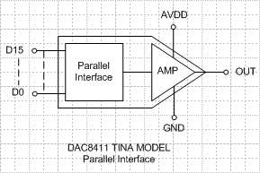
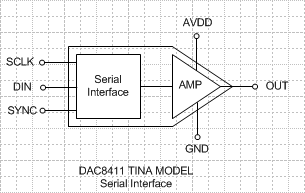
The SPICE models are available in two variants. One uses a simple n-bit wide parallel interface, as shown in Figure 1, which is compatible with all TINA-TI versions. The other model uses a serial SPI interface, shown in Figure 2, and is compatible with Industrial TINA-TI. Both variants include models for the important DC characteristics of the DAC and output amplifier such as offset error, gain error, output voltage swing to rail, temperature drift and quiescent current. Additional characteristics of AC parameters include slew-rate, settling time, power-on glitch and stability. The SPI interface model also completely replicates the digital interface and can be used to simulate the digital signal chain to the input of the DAC.

Figure 1 – DAC8411 Model (Parallel)

Figure 2 – DAC8411 Model (Serial)

Predicting and understanding how a DAC or op-amp will perform when driving a given load is an important aspect of any design. Let’s take a look at an example by simulating settling time with the DAC8411 SPICE model. 

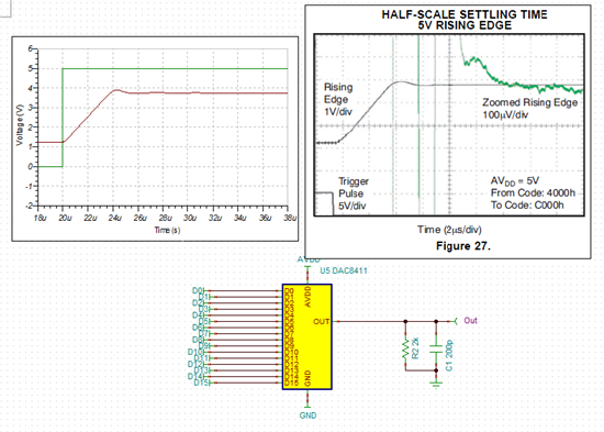
The left-side of Figure 3 shows a transient simulation of the DAC output with a code step from ¼ full-scale to ¾ full-scale. In this simulation the DAC is driving a 2kΩ resistive load in parallel with a 200pF capacitor – the same load used to specify settling time in the datasheet. The SPICE model accurately replicates the settling time of a typical characteristics curve from the datasheet, which is shown on the right side of Figure 3.

Figure 3 – DAC8411 Transient Simulation


But what if you need to drive a load that is different than the load specified in the datasheet? The left side of Figure 4 shows a simulation where the DAC output is loaded with a larger capacitive load of 20nF. In this case, the transient simulation shows considerable ringing, or oscillation, of the DAC output due to instability of the output amplifier with a larger capacitive load. The availability of a complete SPICE model helps catch this problem early so compensation components can be included in first prototypes. 

Figure 4 – DAC8411 Transient Simulation with 20nF capacitive load

Overall, the latest SPICE models for Precision DACs are aimed at giving engineers and designers a unique opportunity to simulate the entire analog signal chain, catch problems early and enable faster time to market. Check out these two TI Precision Designs to see the new DAC SPICE models in action:

  • TIPD158– Low Cost Loop-Powered 4-20mA Transmitter EMC/EMI Tested
  • TIPD160– Digitally Tunable MDAC based State Variable Filter    

Feel free to leave any questions or comments about these new DAC SPICE models in the section below.

JESD204B: Understanding subclasses (part 1)

$
0
0

In this blog, I’ll look at a key feature of the JESD204B standard that defines a method to achieve deterministic latency for each link and subsequently multi-device synchronization. 

Some applications, such as synchronous sampling, multi-channel phase arrays and gain control loops, are sensitive to latency, but the legacy JESD204 and JESD204A data converter interface standards do not provide a defined means to achieve deterministic latency. They rely instead on very strict layout and timing requirements. Thankfully the newer JESD204B standard provides more flexibility. It addresses deterministic latency in three subclasses: subclass 0, subclass 1 and subclass 2.

JESD204B subclass 0

Subclass 0 does not provide support for achieving deterministic latency, but it does enable backwards compatibility to JESD204A while still allowing usage of the higher 12.5Gbps lane rates of JESD204B (JESD204A lane rates were at 3.125Gbps). It also supports alignment of multiple lanes and multiple devices; however, special considerations are required for multiple analog-to-digital converters (ADCs) and digital-to-analog converters (DACs).

When using subclass 0 with multiple ADCs, the RX logic device (FPGA) combines the SYNC signal for each device.  It then distributes the SYNC signal so that all ADCs see the falling edge of SYNC in the same frame clock period. The ADC device clock edge that samples the assertion of the SYNC signal is also used to reset and align internal clocks within the different ADC devices. The ADC device clocks must be phase aligned to achieve synchronization across multiple devices. This requires very tight control on the SYNC, frame and device clocks for each of the ADC devices. 

When using multiple DACs in subclass 0, you’ll need a separate inter-device RX clock synchronization interface to align the internal clocks of the DAC. This ensures time alignment of the RX blocks in each DAC. The TX logic block (FPGA) must combine all of the SYNC signals from each DAC so that the start of ILAS generation at the TX logic block (FPGA) is synchronized across all lanes for the multiple devices.  Figure 1 below shows the critical timing signals required for subclass 0.

Figure 1: Subclass 0 timing signals

Subclass 0 is fully backwards compatible with JESD204A. However, there are some differences in how the timing of the SYNC signal is used for error reporting.  To overcome this, your JESD204B device should allow you to program its error reporting and detection to meet your JESD204A device requirements.

JESD204B subclass 1

Subclass 1 uses an external SYSREF signal as a common reference for multiple devices. SYSREF is source synchronous to the device clock and should come from the same clock source. It can be a one-shot pulse, gapped periodic or periodic signal. In the case of a gapped or periodic signal, the SYSREF must be an integer multiple of the local multi-frame clock (LMFC) to prevent SYSREF from occurring in the middle of a multi-frame.

You can achieve deterministic latency between a TX and RX device when the internal LMFC clocks are aligned to the edge of the device clock when the SYSREF is sampled high. This should also align/reset all the internal clocks of the TX and RX devices. Furthermore, you can achieve multiple device synchronization by ensuring that the deterministic latency is the same for each TX-to-RX link in your group of devices.

The clock chip will generate the SYSREF signal that meets the setup and hold times of the device clock and must be distributed to each group of TX and RX devices with matched trace lengths to ensure proper alignment of the signals.  You should use a clock chip capable of generating both the SYSREF and the device clocks to minimize the skew between the signals.  The timing signals required for subclass 1 are shown below in Figure 2.

Figure 2: Subclass 1 timing signals with trace length matched SYSREF and device clock groups

It is not mandatory for the clock chip to generate the exact same SYSREF for all TX and RX devices, but the clock chip should generate different SYSREFs in such a way that there is a deterministic relationship between when SYSREF is sampled high in all of the devices. In this case, the latency is deterministic but not minimized. 

Figure 3: Multiple devices using different SYSREF and device clocks with a deterministic relationship

Once you achieve LMFC alignment, you can use future SYSREF pulses to check the alignment of the local frame and multiframe clocks. Be sure to turn SYSREF off during normal operation, as a periodic SYSREF signal runs at a sub-harmonic of the sampling clock and may create unwanted spurs.

The subclass 1 system only uses the SYNC signal in the code group synchronization (CGS) process and is not a critical timing signal. 

Stay tuned for my next blog which will give an overview of Subclass 2, which only requires using the SYNC signal (SYSREF not required).

Additional resources:

Protect your power supply from heat and flames

$
0
0

I’ll never forget the first time I saw a power supply overheat and burst into flames.

It was the spring of 2003 and our senior project was on fire (literally) because one of the members of my group tried to run 25W of current through a linear regulator that was probably better suited for about 5W, with no airflow and no heat sinking.  Rookie mistake. Happens to everyone, right?

Aside from my partner’s bonehead miscalculation in college, thermal design for a switching power supply can actually be quite challenging if you aren’t using the right part. Factors like pin configuration, placement of vias, copper area and thickness, and exposed thermal pads all play a big part in keeping your supply as cool as possible and preventing failures (and fire).

The new synchronous SIMPLE SWITCHER family with input voltage up to 60V, and output current to 3A 

With the new family of SIMPLE SWITCHER® LM4360x and LM4600x synchronous converters (see table above), it’s easier than ever to take the black magic out of creating a good thermal design. It starts with the package.

The entire family comes in a pin- and footprint-compatible HTSSOP-16 package. The “H” means that there is an exposed thermal die attach pad (DAP) that helps dissipate heat out of the package as efficiently as possible.  As opposed to other devices that might have multiple DAPs, this family features one large DAP that is connected to ground, which makes it easier to connect to the PCB ground plane as well as effectively cluster vias together to dissipate heat to other layers.

Figure 1: Optimal heat spreading is possible with an unbroken copper ground plane in the “dogbone” shape, connected to the DAP

Having pins on two sides of the package instead of four also works to our advantage. This means the copper ground plane does not need to be broken by the routing of signals, and can be formed into a dogbone shape that allows optimal spreading of heat away from the device (see Figure 1).

Figure 2: LM43603, 12Vin to 5Vout, 3A output, 500kHz, 24.3°C ambient temperature

The cherry on top is that this excellent thermal performance can all be simulated for free using TI’s WEBENCH® online design tool. You can start a WEBENCH design using your Vin, Vout, Iout, TA input parameters, and click the “thermal” tab (looks like a thermometer) once you have chosen a device to design with. From there you can enter parameters for ambient temperature and copper weight, while simulating air flow to get strong indications of how the device will perform in your design (see Figure 2).

Taking this even one step further, you can also download the layout from your WEBENCH design and copy and paste it right into your CAD tool. Watch this video for a detailed look at how to do it. So if you’re looking for an easy way to design your system with good thermal performance and reliability, look no further than the new SIMPLE SWITCHER LM4360x and LM4600x synchronous converter family. For more details, check out the thermal Design Made Simple App Note and video

Input overvoltage protection enables higher efficiency and lower cost power supplies in automotive applications

$
0
0

There are numerous power supplies in the modern day automobile.  The increasing number of electronic circuits require their own power supply, which creates a power draw and cost hurdle for designers.  Additional electronics are needed for new safety features, more infotainment options, extra driver assistance systems, and so on.  The cost of these new circuits adds up in the R&D effort and in the car price.  The power consumption of these new circuits shows up in your MPGs and in your gasoline bill.

The power supply design for each electronic system is critical.  For those electronics powered directly from the battery, the power supply must safely withstand a wide range of input voltage transients applied to it.  These voltage transients may occur when the car is started or when the air conditioning or another motor turns on or off.  This wide input voltage range increases the cost and power consumption of the power supply by requiring higher breakdown voltage transistors, which are already more costly and inefficient.

However, several of these electronics do not need to be powered all of the time.  Certain infotainment systems and the USB ports found throughout an automobile are not safety critical.  These systems can tolerate brief power outages, if it makes their design more efficient and lower cost.  If they could be protected from the brief input voltage transient, these electronics would not need to be rated for the very wide battery voltage and suffer the corresponding efficiency loss.

This is a job for the PMP9757 design: Step-Down Converter with Input Overvoltage Protection.  By using an overvoltage protection circuit to insulate the power supply from the battery, the power supply  can be designed to better optimize the cost and efficiency of the given electronic system. For example, the 17-V rated TPS62150A-Q1 could be used with PMP9757 to generate a 3.3-V rail from the 12-V nominal battery, instead of needing to use the 60-V rated TPS54160-Q1.  Using the TPS62150A-Q1 instead enables a 90% efficient power supply with a substantial IC cost and BOM count reduction.

Which of your automotive sub-systems could benefit from input overvoltage protection?

50th Founder’s Day celebrates TI and UTD collaboration

$
0
0

The link between TI and the University of Texas at Dallas (UTD) is deep and vast – beginning with the two organizations sharing the same founding fathers: Eugene McDermott, J. Erik Jonsson and Cecil Green. Hungry for top engineers to fuel the company’s growth after its launch in 1951, TI business leaders found themselves “importing” talent from other parts of the United States, while Texas’ best and brightest math and science students left the Lone Star State to pursue their education elsewhere.

As a response to the shortage for PhD-level engineering talent, McDermott, Green and Jonsson established the Graduate Research Center of the Southwest in 1961, which would go on to become UT Dallas. 

On October 29, 1964, the first campus facility was dedicated, appropriately named the Founders Building after the three men who saw a brighter math, science and engineering future in North Texas. Yearly celebrated as Founder’s Day, TI and UT Dallas will commemorate the 50th anniversary on Wednesday, Oct. 29 from 4-5 p.m., unveiling busts provided by TI to honor the vision and legacy of McDermott, Jonsson and Green. Participants will also hear from TI representatives and guest Philip Jonsson, son of J. Erik Jonsson.

The three founders donated the center and its lands to The University of Texas system in 1969 to officially create The University of Texas at Dallas. In 1986, UT Dallas established the Erik Jonsson School of Engineering and Computer Science, which plays a critical role in providing a highly educated work force for the advanced technology industry. 

Thanks to the vision of McDermott, Green and Jonsson, UT Dallas is nationally recognized, with US News and World Report ranking it as one of the three best public universities in the state along with the University of Texas at Austin and Texas A&M. TI hires more than 60 UT Dallas graduates yearly from its ongoing pool of talent, with more than 500 currently working at the TI corporate headquarters in Dallas.

“We see UT Dallas not only as an investment in our own company, but an investment in the economy that pays off with innovation, leadership and jobs,” said Steve Lyle, TI director of university and engineering workforce development.

Thanks to UT Dallas’ leadership, TI has seen unprecedented collaboration among the schools at the university, creating value-added programs such as The Institute of Innovation & Entrepreneurship, the Material Sciences Program, the Systems Engineering Program and the Asia Center, to name a few. 

“All these programs are the continued realization of our joint founders’ dreams,” added Steve. “We are proud to continue supporting the legacy left behind by Eugene McDermott, Erik Johnsson, and Cecil Green.”

Learn more about the UTD Dallas Founder’s Day celebration.

Read about Jonsson’s community leadership and dedication to the future of engineering.

The importance of proper termination

$
0
0

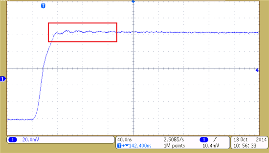
I recently performed some tests in the lab and noticed a strange ringing on the output signal. After troubleshooting the problem, I managed to trace the ringing back to the input signal. Figure 1 shows the input signal of my circuit with the ringing boxed in red. I needed to find the cause of the ringing since a clean step response was expected. It turns out that my lab equipment was not properly terminated. This blog post describes how to properly terminate your lab equipment and the importance of this technique.  

Figure 1: Unknown ringing

Figure 2 shows the test circuit with source impedance, ZS, equal to the default 50Ω source impedance of the lab equipment and input impedance Zi.- These can vary depending on what is needed for the circuit.

Figure 2: Test Circuit

Using the reflection coefficient equation, shown in Equation 1, it is possible to see that if the input impedance is not equal to the source impedance, the reflection coefficient will be a non-zero value.

Equation 1

Setting Zi which is much greater than ZS, gives a large reflection coefficient. As shown in Equation 2, setting Zi equal to 1MΩ gives a reflection coefficient of approximately 0.9999. This means that almost the entire input signal reflects back to the function generator and results in ringing. 

Equation 2

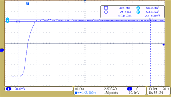
Figure 3 shows an oscilloscope shot of a measurement taken at the input of the OPA350 with Zi equal to 1MΩ. This shows a ringing with a peak-to-peak voltage of 4.4mVpp.

Figure 3: Input waveform with Zi=1MΩ

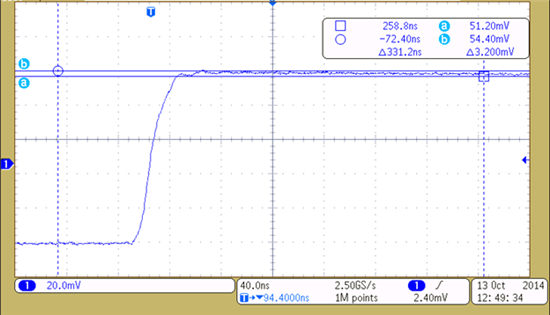
To decrease the peak-to-peak voltage of the oscillations, minimize the reflection coefficient. For example, reducing Zi to 1kΩ, gives a reflection coefficient of 0.905. This will reduce the magnitude of the voltage reflected back to the function generator. Figure 4 shows an oscilloscope shot of a measurement taken at the input of the OPA350 with Zi equal to 1kΩ. Notice the reduction of peak-to-peak voltage to 3.2mVpp.

Figure 4: Input waveform with Zi=1kΩ

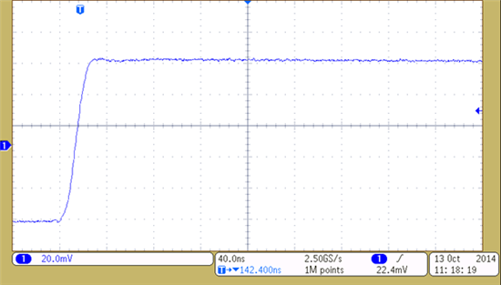
To properly terminate the lab equipment and eliminate the reflections, Zi must be equal to the source impedance of 50Ω. Figure 5 shows a measurement taken at the input of the OPA350 with Zi equal to ZS. Notice how the ringing will stop. 

Figure 5: Input waveform with Zi=ZS

Properly terminating your lab equipment with a circuit input impedance equal to the source impedance of the equipment is crucial for a clean input signal. Next time you find yourself wondering where an unknown ringing is coming from, remember to check that your lab equipment is properly terminated. 


DIY with TI: Mastering homebrew with a TI-inspired kit

$
0
0

What did Leo Estevez get when he combined an MSP430G2553 microcontroller (MCU), our NexFETs, Bluetooth and power management components? A remote-control drone car and a microbrewery.

Leo created a virtual machine called “Rekam1,” which allows users to follow the same simple instructions to build and program a variety of products. The do-it-yourselfer used the same electronic board to power his popular REKAM-DR1 programmable car as he did for his home-brew kit. 

(Please visit the site to view this video)

“Our low-power MCUs are designed to cover a variety of applications,” Leo said. “Coupling our NexFET power transistors and range of power management solutions with these low-cost MCUs is what makes things flexible from a hardware perspective.”

Let’s talk beer

To make a home-brew kit, a DIYer can use an iPhone or Android phone to program the Rekam1 kit to circulate water with two food-grade pumps between two pots – a hot pot and a grain pot – to extract the sugars from malted grain.

Basically, the brewmaster boils the sugary liquid (called wort) with hops and then pumps the wort back to the cooling pot for fermentation.

The brewing process takes about four hours, while fermentation can be anywhere from a week to several months.

“This is how commercial breweries work,” he said. “I just miniaturized it and added a wireless connection for programming via your phone. This contains everything you need to brew beer from grains.”

Brew it yourself

Leo produces the Rekam1 boards primarily for student learning projects like the REKAM-DR1 drone, which became a fully funded Kickstarter project in April.

Precision Technology Inc. produces the Rekam1 boards for Leo at a cost of $39 each, including parts and manufacturing costs.

Leo’s phone app is free and open source and can be downloaded from www.github.com/leonardoestevez/Android . The hardware also is open source, and schematics can be found at www.github.com/leonardoestevez/Hardware.

About Leo

Leo has worked with us for 17 years and is an electrical engineer and technology strategist at Kilby Labs. He previously worked as an embedded systems contractor for a company that made chemical analyzers and chemical digestive systems using our DSPs.

He has been brewing beer for about 20 years, but he started incorporating our devices into his brew kits a few years ago when our MCU LaunchPad first became available.

Leo does not consider himself a beer connoisseur, but he has tasted some experimental brews for large beer companies. And he appreciates a good Hefeweizen in the summer and Guinness in the winter.

He and his friends have been very pleased with his home-brew creations.

“Drinking freshly made beer as it is aging towards its ‘peak’ is something few people experience. The beer changes quickly immediately after fermentation and then mellows out into the final product over a few months,” he said. “I think most folks enjoy tasting the beer as it ages. The fact that there is an unlimited supply of whichever batch you like best is nice, too.”

Increase battery life with low voltage monitoring

$
0
0

In this day and age low power consumption is something every system is moving towards,  making it a key challenge for engineers to minimize power for their application. Low power consumption is something we can all agree on especially when it results in lower electricity bills and longer cell phone batteries.

In our efforts towards helping system designers reduce power consumption the newest knight in our family is TPS3847, the 380nA Iq, 18V - the industry’s lowest power voltage monitor. 

A voltage monitor by nature is an ‘always-on’ device. The supply voltage is always monitored even in standby mode, which makes it necessary to have low Iq voltage monitors for the next generation of products. For example, when a line power device is in standby mode for a long time, such as a desktop or home appliance, the supervisor is still on and working. In battery powered applications such as power tools or portable medical equipment, the user is looking to achieve a longer battery life between recharges. Adopting the use of a low Iq voltage monitor can effectively increase system efficiency and improve energy star ratings.

TPS3847 is a voltage monitor ideal for monitoring 12V applications while consuming only 380nA of current. TPS3847 offers a push pull logic removing the need for a resistor on the output and still works with most common logic levels.  The product also offers +/-2.5% accuracy over its temperature range and is available in industry standard SOT23 package.

Check out the device for your 12V needs, reduce power consumption up to 100x and let us know what you think in the comments below! 

A new “spin” on motor control for electric vehicles

$
0
0

As electric vehicles steadily gain popularity around the world, companies are working harder than ever to implement motor control technology that keeps the motors in these vehicles spinning as efficiently as possible. To reduce emissions and dependence on fossil fuels, certain countries around the world implement emission-free zones where vehicles are required to apply full electric operation. e-Traction, a company that develops powertrain technology for electric vehicles, is using our C2000™ Piccolo™ microcontrollers (MCUs) and InstaSPIN-FOC™ motor control technology to ensure vehicles meet these regulations.

e-Traction created the MD series of motor drives after the company realized there was no off-the-shelf drive on the market that could provide electric vehicles with a drive as efficient, reliable and safe the company could create. Each motor drive ranges from 25 amps to 450 amps so the company can provide drive solutions for different types of applications inside the vehicles.

In Rotterdam, Netherlands, e-Traction is using the MD series to electrify city buses to meet the standards of emission-free zones. Within these zones, the standard diesel engine shuts off, and C2000 Piccolo MCUs control electric drives that run in-wheel traction motors as well as auxiliary motors for compressors, fans and water pumps. Outside of the emission-free zones, InstaSPIN-FOC technology is used to control the electric starter motor that starts the diesel engine, and then the same electric motor is controlled as a generator to recharge the batteries. The result is a “maintenance-free, efficient, silent and fast-starting solution compared to our competitors,” according to Geert Kwintenberg, engineering manager for e-Traction.

Watch the video below to learn about some of the biggest challenges e-Traction faced when creating its MD series, and how our C2000 real-time control MCUs helped the company find control solutions that consume less energy and are applicable to several different kinds of motors and power levels.

video platformvideo managementvideo solutionsvideo player

Are you working on other environmentally friendly applications located “behind the wheel”? Leave us a note and let us know!

For more information

Battery Management: A Meeting of the Minds

$
0
0

Some of you reading this have come to our annual battery management seminar in Dallas, either this year or sometime over the past 10 years. In 2004, we started this event with a handful of engineers from one customer who wanted to get help programming their fuel gauge chips for better performance and tips on how to optimize their manufacturing flow. We provided insight in an all-day meeting in one of the conference rooms at our factory and then went out for Chinese food before they left the next morning. We’ve come a long, long way since then.

We’ve steadily grown, and now the annual TI Battery Management Deep Dive has evolved into an industry event. This year, 230 engineers from 75 different companies around the world traveled to Dallas for three days of interactive discussions about a wide variety of topics. Our experts in several areas such as electrochemistry, passive components, circuit design, embedded firmware, pack and system safety, and more were ready to provide insight and tips as well as share past experiences. The combined talent in one room between TI staff, our partners, and customers was really awe inspiring. It was the global economy in one room!

This was the best and biggest conference we’ve had so far, but we’re already thinking about how to make next year’s seminar better. If you want to join in, think about coming to Dallas next year in October! You can see this year’s agenda at our Battery Management Deep Dive page. If there is a particular topic that you would like to see next year – please leave a comment and let me know!

For more about battery management trends and design tips, keep an eye out for posts on the Fully Charged blog.  

And for details on battery management products and design resources from TI, visit ti.com/battery.

Timing is Everything: JESD204B subclass 1 clocking timing requirements

$
0
0

Most of the JESD204B standard addresses the data interface between logic devices and converters, so what are the clocking requirements? For JESD204B subclass 1, the clocking requirement is quite simple: use the SYSREF rising edge to mark the device clock rising edge which resets the local multi-frame clock (LMFC) of the JESD204B element. Now let’s discuss how to achieve this requirement.

The datasheet of the logic device or converter will indicate the timing requirements for placement of the SYSREF rising edge with respect to the device clock rising edge. Figure 1 illustrates a typical valid SYSREF window after considering set-up and hold timing requirements. Note, only the rising edge of the SYSREF clock waveform is shown. The SYSREF clock may remain high across multiple device clock edges. Only the rising edge of SYSREF marks the device clock edge which resets the LMFC.

Figure 1: Example of valid SYSREF window: Green arrows 2 through 8 indicate valid SYSREF positions  that cause an LMFC reset on device clock edge located at position 11

It is possible to ensure accurate SYSREF placement by careful routing of SYSREF and device clock traces on the PCB, which factors all skew elements. However, if there is an error in design of the PCB, then re-spinning the PCB may be required to resolve the timing problem since a marginal SYSREF rising edge may result in different device clock edges being used to reset the LMFC from power-up to power-up or across devices. This results in a source of non-deterministic latency, which cannot be eliminated by using the RX Buffer Delay. Depending on the application, this +/- integer device clock cycle error of LMFC edge position between JESD204B devices may or may not be acceptable.

One solution to ensure a good placement of SYSREF rising edge with margin is to use a clocking device, such as LMK0482x, which supports delay adjustments of the SYSREF and/or device clock. When using a clocking device with delay adjustments, it is possible to simplify PCB design by relaxing or eliminating trace matching requirements because relative SYSREF and device clock phases may be skewed by programming the clock device. Figure 1 illustrates a delay that’s able to adjust the SYSREF rising edge position in 200 ps steps. Shown are seven SYSREF rising edge positions that meet the set-up and hold time, but position 5 gives the most margin to the edges of the set-up and hold windows and is the preferred placement to use in this application.

By designing a system that allows the placement of at least four edges inside a valid SYSREF window, margin of approximately the step size can be ensured in the design. In high-speed systems it may not be possible achieve small enough delay steps to have four placements of SYSREF in the valid window. Figure 2 illustrates three different cases when only two placements of SYSREF are possible in the valid window: (a) placement in middle of window, (b) one placement on edge of window, so other placement has margin, and (c) both placements have equal margin.

Figure 2: Example of valid sample windows for high-speed clocks: Red arrows show smallest margin to edge of valid SYSREF window for each case

The margin for each case in Figure 2 may be calculated for you own system as shown in Table 1.

Figure 2 Case

Approximate Margin

(a) Best

Valid window / 2

(b) Intermediate

Valid window – Step size

(c) Worst

(Valid window – Step size) / 2

Table 1: Timing margin calculations for two SYSREF placements in valid SYSREF window

In these high-speed cases, some giga-sample data converters, such as ADC12Jxxxx, allow shifting the valid window with a very fine delay step to improve SYSREF margin. Some extra considerations in the SYSREF timing margin is that the non-uniform delay step size and jitter can reduce margin.

Finally, there are no phase noise or jitter specifications for the SYSREF clock in JESD204B. However the SYSREF period peak-to-peak jitter plays a small part in the timing margin for SYSREF.

Thanks for joining me, and be sure to check out other blogs in the Timing is Everything series and the JESD204B series.

Additional resources:

Viewing all 4543 articles
Browse latest View live