Choosing something as simple as a linear regulator is often a lesson in thermal dynamics. The designer usually realizes their error after the design is on the bench. Or worse, the design fails in the field because a regulator is running beyond its temperature...(read more)![]()
↧
Watt’s wrong with my LDO?
↧
Microcontrollers, wireless connectivity and analog solutions for industrial applications

The most effective industrial solutions require products that meet harsh environment and long-operating-life standards, with the flexibility to integrate the latest technologies like wireless communication.
We just hosted a webinar in December that walked through various industrial reference designs and discussed various microcontrollers, wireless devices and analog ICs optimized for industrial applications. It touched on TI's broad portfolio and how our extensive support resources can help address your industrial system challenges.
Since we received such a positive response to this content, we made sure this webinar was made available on demand. You can access it here.
↧
↧
Robotics feeds maker interest for disadvantaged teen
For 18-year-old Quentin Neroes, robotics has been a difference maker.
 Quentin has always had an interest in science and math, but his family didn’t have the funds for him to create maker projects or even to purchase a subscription to his favorite magazine, Astrophysical Journal. To feed Quentin’s maker interests and provide him with a high school education that would better prepare him for college, his mother enrolled him at Emmett J. Conrad High School in Dallas, a school offering a STEM (science, technology, engineering and math) Academy, and most importantly, a robotics program.
Quentin has diligently participated in the school’s robotics club since his sophomore year, despite his mother’s early skepticism (at first she thought it was nothing more than fun and games) and the difficulty of the commute to make the after-school sessions.
Quentin, who hopes to become an astrophysicist, has been accepted to Harvard University, although he is hoping to attend Princeton or MIT. His studies include AP Calculus, Physics and Chemistry, and he’s the student council president. But Quentin points to robotics, with its perfect mix of technological challenges, creativity and mentoring, for giving him opportunities kids in his neighborhood don’t typically get to experience.
“Robotics has boosted my goal-chasing and nurtured my competitive spirit. With this spirit, I am even more determined to gain entry into the colleges that I want to consider,” said Quentin. “I enjoy robotics because it is a way to explore my creative side by making something new, and it is an opportunity to learn from experienced engineers and observe how they operate.”
Today, Quentin and his high school team − the FRC3005 RoboChargers – are veterans in the FIRST® (For Inspiration and Recognition of Science and Technology) Robotics Competition, entering their seventh year of competition. Quentin and his team get to see real-world applications to the engineering, science and math they learn in class each day, with hands on experiences. But Quentin says the greatest benefit of the program is spending time with mentors like TI engineer Steven Smith.
 “Steven’s influence is one of the reasons mechanical engineering is interesting to me now,” he said. “He also has helped me become a stronger person by showing me how a leader behaves. While leaders have the most power in a group, they must also listen to suggestions and rule nothing out. As a scientist, this is imperative.”
Steven downplays his influence, seeing his contribution as a small part of the solution when it comes to influencing kids like Quentin to pursue an interest in STEM. But he admits the opportunity to meet real-life STEM professionals can have a lasting impact.
“A professional adult mentor can help support teachers, provide guidance like a parent and help motivate students with a reason to learn,” Steven said. “It ultimately provides a pathway to success with skills that are critical in industry.”
During the upcoming FIRST robotics season, Steven and all of the team’s 15 mentors are especially supportive of their students’ interests, including Quentin’s desire to specialize in computer-aided design (CAD). When Quentin’s not modeling the robot in 3D, he’ll also become “a jack of all trades,” helping members in all of the other specialties and serving as a scout during the tournament to assess the strengths and weaknesses of their other teams. This role is critical to ensure his team picks strong partners, as they compete with hopes of progressing to the World Championship this year.
But for the next six weeks, Quentin’s challenge is building the best robot, juggling commutes and classwork and student council, and gleaning as much as he can from Steven. As for the next challenge on the horizon, that’s entirely up to Quentin.
↧
A Fresh Start for 2015 – Ford and TI collaborate on SYNC® 3
Now that we’ve closed out 2014 and launched full steam into 2015, I hope everyone had a chance to get away and enjoy time with family and friends. My family and I over the holidays enjoyed a new experience – plentiful amounts of snow in Colorado! (For a family from Texas, you’ll understand the significance of this.) As I watched my children’s reaction to this foreign substance, I reflected on how exciting new experiences and new products can be. And with snow, especially, it’s such a great reminder of fresh starts and new beginnings.

In this same spirit of new beginnings, Ford Motor Company and Texas Instruments announced at CES 2015 the collaboration on the newly-announced Ford SYNC® 3, which leverages TI’s OMAP™ 5 processor, a member of the “Jacinto” family of automotive processors, the WiLink™ 8Q platform, a single-chip combining high performance Wi-Fi®, Bluetooth® 4.0 and GNSS, as well as power management and FPD-Link III serializer/deserializer (SerDes) wired connectivity solutions. Our automotive solutions work together within the SYNC 3 system to provide an improved connected driver experience.
The focus of the improvements of Ford’s SYNC 3 are centered on improved overall performance, especially with the user interface and touch screen performance, more conversational voice recognition, and smartphone integration and control. The OMAP5 processor provides the foundation for all of these expanded capabilities by including a combination of multicore ARM Cortex A15 CPUs, multicore 3D GPUs, and optimized memory interfaces. OMAP5 also serves as the first of the “Jacinto 6” family of automotive processors, which are geared to blend performance, scalability, and automotive bill-of-material optimization.
Leveraging the latest generation ARM® Cortex®-A15 multicore CPUs and Imagination Technologies' POWERVR™ graphics cores, together with the highly-integrated WiLink 8Q wireless connectivity solution, Ford can offer a system with a snappy user interface and high-quality multimedia parallel to a premium connected car experience with Wi-Fi, Bluetooth and accurate navigation data. To accurately deliver high-definition video and audio to the color touch screen, TI’s FPD-Link III SerDes wired connectivity chipset provides the high-speed connection over a single twisted wire pair, which minimizes the complexity, cost and weight of the solution. WiLink 8Q’s Wi-Fi capabilities are also utilized to enable consumers to seamlessly update software over the air, at home; more in line to processes consumers use with smartphones and tablets today.

If you didn’t have a chance to see the SYNC 3 at CES 2015, this exciting new technology from Ford and TI will be showcased this week at the North American International Auto Show in Detroit as well as other shows throughout the year!
Read more about the collaboration between TI and Ford here and watch the video live from CES 2015.
↧
Check out latest reference design for Resistance Temperature Detector for Grid Infrastructure
Temperature is one of important parameters need to be monitored in the power system. For example, as expensive and critical component of power system, a large of number of transformers have been deployed on the transmission and distribution power grids. Due to long lead time for repair and replacement, temperature-based protection can limit the damage to a faulted transformer by identifying operating conditions. Along with smart grid migration, the industry demands accurate, repeatable, and reliable measurement of temperature, which can have a significant impact on the cost, quality, efficiency and safety.
Temperature measurement was one of oldest known technologies, there are different ways to do so based on different sensor adopted, such as thermistor, thermocouple, and resistance temperature detector (RTD). The focus of this design is to measure temperature using RTD, a sensing element whose resistance changes with the temperature. The relationship between the resistance and temperature of an RTD is highly predictable, which allows accurate and repeatable temperature measurement over a wide range.
RTD requires constant current source for its excitation to produce a voltage output proportional to the resistance of the RTD. The resulting voltage output is measured by the analog-to-digital converter (ADC). In this design, there are couple of nice things I want to share with you,
- With same hardware, this design is carefully developed to support different lead wire configuration, such as 2-wire RTD, 3-wire RTD or 4-wire RTD.
- Higher resolution ADCs with PGA (Programmable Gain Amplifier), which match current source and radiometric measurement techniques, are used to improve accuracy.
- Furthermore, to minimize the noise impact on accuracy, which can be found in excitation source, and ADC reference voltage drift, a ratiometric approach is considered in this design with selected low-tolerance, low drift reference resistor.
- Finally, this design coupled with MCU board shows < ±2°C accuracy over wide range without calibration.
For more details, check out on ti.com at http://www.ti.com/tool/TIDA-00110
↧
↧
Two-Wire 4-20mA Transmitters: Background and common issues (Part 3)
Part 2 of this blog series derived the basic transfer function for a typical two-wire transmitter, commonly used in industrial control and automation, and explained the currents flowing inside it. It also explained that connecting the transmitter return (IRET) to the loop supply ground (GND) prevents proper operation of the transmitter.
Today’s post discusses the current consumption limits of the circuitry that is powered from the VREG and VREF outputs.(read more)![]()
↧
BOM-optimize your vacuum cleaner!
In the consumer world with products, such as vacuum cleaners and white goods, the Bill of Materials (BOM) is extremely important. The broad array of products and companies designing those products create great competition—pressuring pro...(read more)![]()
↧
Replacing multiple devices with one? That’s good logic.
Logic ICs are handy devices engineers sprinkle in for quick translation fixes in their designs. However, simple fixes along the way sometimes complicate things even more. There are many reasons why an engineer would choose to use a logic device in their application. (read more)![]()
↧
Automotive Trends: Cameras in Every Car

One major trend that we’ve all noticed in automobiles over the past few years is the use of cameras-- for assistance when backing up. Just 10 or 20 years ago, such technology was unheard of in the United States. By 2018, it will become mandatory in all new vehicles. Some automobile manufacturers are even looking to install more than one camera per vehicle to provide more driver assistance and safety. Clearly, this market is becoming essential which demands an optimized yet flexible design, allowing for design compatibility across a number of different models.
Almost all of these cameras receive their power from a protected and semi-regulated form of the battery’s voltage. The individual camera does not need to incorporate all of the expensive and bulky circuitry necessary to operate directly from the battery and to support the voltage transients that come with cold crank and other harsh operations. This configuration reduces the cost and size of each camera.
On the other hand, the power supplied to the camera is not from a perfectly regulated source. To reduce weight, the power wires are typically very thin. In other cases, the power is delivered over a coaxial-type cable (“power over coax”) and not dedicated power cables. This method reduces the extra weight of all cables.
In either case, such thin cables necessarily have significant voltage drop across them. This causes the voltage at the camera end of the cable to vary dramatically based on the length of each cable to each camera. Different vehicle types have different lengths of cable, creating the need for a flexible solution for common power architecture, which can be used for all vehicle cameras. Such a solution needs to be small and cost-effective.
This TI Design shows a flexible, small, and cost-effective solution for a camera module. The solution shown above next to a USA quarter-dollar coin uses the automotive-qualified TPS62170-Q1 to operate directly from power sources such as coaxial cables. The wide 3-V to 17-V operating input voltage range makes this device well-suited for a variety of semi-regulated input power sources. The 2-mm x 2-mm IC package enables a total solution size of under 50 mm2. A second voltage rail on this camera module reference design is created from the smaller TPS62231-Q1, which comes in a 1-mm x 1.5-mm IC package., supporting a 12-mm2 total solution size.

In addition to the small IC size and high integration enabling a very small total solution size, the DCS-Control topology of these two devices gives excellent noise performance and eliminates the need for post-switching converter linear regulators (LDOs). The noise performance of these two switching converters is sufficient for the application with simple and low cost resistor-capacitor (RC) filters installed where needed. A higher efficiency solution with lower self-heating and less Bill of Materials (BOM) cost results.
What trends do you see in automotive camera modules?
↧
↧
On the Fringe: It’s all about the packaging
The holiday season just ended - a time of year when gift givers everywhere take time to carefully wrap presents with colorful paper and festive bows. And while we devote so much effort and energy to special packaging, the gifts inside far outwe...(read more)![]()
↧
SAR ADC response times: Interface topology makes a difference
In my previous blog post, I explained the differences between a SAR ADC’s throughput and response time. Today, let’s see how an interface topology affects the throughput and response time of a SAR ADC.(read more)![]()
↧
CES 2015: All about IoT connectivity

As Monica Alleven from FierceWireless proclaimed, “you'd have to be hiding under a blackjack table to miss the barrage of Internet of Things (IoT) rhetoric pouring out of the panels, press conferences and exhibitors at the Consumer Electronics Show.”
Last week TI gathered in Las Vegas with innovators from around the world at the International Consumer Electronics Show 2015 (CES) where technology makes anything seem possible.
The show floor highlighted the best of the best in the latest tech inventions, foreshadowing what the top trends will be for 2015. Unfortunately, the week had to come to an end, but we made quite a splash and are already looking forward to what CES 2016 will bring.
Among the plethora of revolutionary products at the event, TI's wireless connectivity solutions, including the SimpleLink™ Wi-Fi®, Bluetooth® Smart and WiLink™ 8 platforms were highlighted across a wide range of demos in the TI Village and across the show floor. End products featuring TI tech included the Ford SYNC® 3, Bluvision’s iBEEK™ Beacon, Motionize’s Bluetooth Smart Paddles, Butterfleye’s Smart Camera and WeFind’s wearable IoT for proximity interactions as well as tech demos that showed off home automation, low-power NFC bio-patch sensors and Wi-Fi audio synchronization.
Check out the videos listed below to see how we enjoyed CES!
- WiLink 8 Wi-Fi Bluetooth Solutions: Audio time synchronization
- TI and Ford SYNC 3: Redefining User Experience
- Automotive Wireless Connectivity with WiLink 8Q
- Bluetooth Smart Paddles Maximize Your Kayaking Performance
- Butterfleye Smart Camera: Simplelink Wi-Fi CC3200 Wireless MCU
- Designing Ultra-low-power Bio-patch Sensors with NFC
- WeFind: Wearable IoT for proximity interactions with SimpleLink Wi-Fi®
- CES 215 Preview: Connectivity Technologies
- Experience Your TI: CES Day 4 – IoT connectivity
If you would like to learn more about our demos or products, let us know in the comments section below. You can also check out TI’s complete CES 2015 YouTube playlist.
↧
Making Ideas Real. 3D Printer Technology From TI!
3-D printing technology has exploded over the last few years! It seems as if every other day you are hearing a new story where 3-D printing is taking the lead. Just recently, I read about the first 3-D printer in space. NASA hopes that 3-D printing will one day provide a resource for printing spare parts on the go and creating many of the materials necessary if we ever hope to colonize another planet. 3-D printing would allow an isolated station or outpost the ability to use its limited resources wisely, instead of planning ahead for every worst case scenario. This flexibility is one of the keys ideas driving 3-D printing.

Now, I am not going to get into the details of 3-D printing. That is a conversation for another time. If you want a deeper background on 3-D printing I suggest giving this article a good read.
Instead, today I’ll give you some insight on how TI fits into the 3-D printing revolution. We decided what better way to do so than build our very own 3-D printer? The end result was a 3-D Printer ControllerTI Design based upon the LaunchPad + BoosterPack configuration that utilizes a broad array of TI devices. Many of these devices were designed to make life easier when designing your own 3-D printer system.
TI Design: 3-D Printer Controller

Let me give you a brief rundown on each device and its purpose in the 3-D printer.
- DRV10983: Most 3-D printers utilize some sort of cooling fan for the either the extruder heater or the electronics themselves. Many cooling fans utilize a 3-phase BLDC motor, which while efficient, does require some work to spin properly. The DRV10983 makes 3-phase BLDC simpler by integrating a sensorless control scheme to get your motor spinning in minutes. To learn more, check out this blog on the DRV10983.
- DRV5033: One key requirement in 3-D printer systems is to precisely know the location of each axis. This can be accomplished in many ways, but one of the most common utilizes stepper motors with limit switches. Oftentimes, designers will utilize a mechanical limit switch but we wanted to take the next step and go contactless. The DRV5033 Hall sensor detects when a magnet has reached within a certain proximity to the sensor. The DRV5033 then signals to the MSP430™ microcontroller (MCU) that the axis has reached the end of its track. With this, the MCU now knows the absolute position of the axis and can use the stepper motor to maintain an exact position of the axis.
- CSD18534Q5A: The three power MOSFETS in our design are used as load switches to drive the extruder heater, hot bed heater and an external fan. This power MOSFET, while like many others, gives you quite the bang for your buck. A high-power MOSFET in a compact package can be crucial in these sorts of applications where board space and heat sinking is limited. Another feature of the CSD18534Q5A is the ability for it to be driven directly from the MCU, saving you even more precious board space.
- UA78M33: While never in the spotlight, no system is complete without a trusty LDO. The UA78M33 takes the main power supply for the motors/heaters and regulates it down to 3.3V for the MCU and sensors.
- DRV8846: The backbone of the 3-D printer, the stepper motor driver. Without these guys, we aren’t getting anywhere. Most 3-D printers utilize stepper motors to move the extruder in addition to each axis. The four DRV8846s make stepper control simple with their adaptive decay current regulation scheme that automatically adjusts for your specific motor. To learn more about the DRV8846 you can check out this blog.
- MSP430F5529 MCU: If the stepper motor driver is the backbone, the MCU is the brain. The ultra-low-power MSP430F5529 MCU lets you take control of your 3-D printer and starting bringing objects to life. With integrated USB support, the MSP430F5529 can easily interface with a host PC, or you can look to load designs from another storage medium such as micro-SD. The wide array of peripherals allows you to easily command the various subsystems of the 3-D printer while still maintaining the low-cost nature of the MSP430 MCU family.
Well that’s all the time we have for today. It’s time for you to get out there and starting designing your own 3-D printer! If you have any questions or want more information, you can visit the TI Motor Driver Forums or check out the TI Motor Drive & Control Home Page.
Nick
Nick Oborny, Motor Applications Team, Texas Instruments
↧
↧
JESD204B: How to calculate your deterministic latency
In my previous blog, I explained how to achieve deterministic latency by aligning the LMFC signals at the transmit (TX) and receive (RX) devices and using the release buffer delay (RBD) to set the data release point to follow the expected arrival of the latest arriving lane. In this post, I will show you how to calculate the expected link latency using device parameters of the TX and RX devices.
Total latency is the sum of the analog-to-digital converter (ADC) core latency plus the link latency. ADC core latency can usually be found in the ADC datasheet. Link latency is defined as the time when samples enter the TX serializer, traverse the SERDES lanes, go through the RX de-serializer and come out of the elastic buffer. This is shown in figure 1.

Figure 1. Summary of the total latency from signal input to parallel out (S2PO). It is comprised of the ADC core latency and the JESD204B link latency. You can adjust the elastic buffer to optimize link latency.
You can calculate the link latency using the following information, which should be available from the TX and RX device vendor:
- Determine the alignment of the TX and RX local multi-frame clock (LMFC) with respect to the arrival of SYSREF (subclass 1). Any offset between the TX and RX LMFC will be accounted for as a fixed delay. The device datasheet for the TX and RX typically provides this parameter as some number of frame clock cycles. The difference is given by tRX_LMFC-tTX_LMFC.
- Calculate the expected link delay accounting for system variations. The link delay starts at the TX LMFC edge and ends at the RX de-serializer output. The link delay is the sum of the TX serializer delay tTX SER, the lane delay tlane and the RX de-serializer delay tRX SER.
- Choose the elastic buffer release point that provides margin against delay variations. Typically, the elastic buffer release point is set at the next LMFC edge following the arrival of the last lane. In this case, the RBD is set by default to K frames (1 MultiFrame) from the prior LMFC edge. This causes the data to release at the next LMFC edge following the arrival of the last lane. However, if all the lanes, including system variations, arrive at some point in between LMFC boundaries, the RBD can be set less than K to optimize the link latency.

Figure 2. Link latency starts from the TX LMFC to when the data is released from the Elastic buffer. RBK<K can be used to optimize the link latency.
Once you’ve done this, you can calculate the link latency as the composite of the delays from the TX LMFC edge when the data enters the TX serializer to when the data comes out of the Elastic buffer. This includes the difference between the device TX-RX LMFC edges, some integer number of multi-frames spanning the link delay and the RBD number of frames in the elastic buffer. The total latency would then be the fixed ADC core latency + the link latency. This can be expressed as a function of the frame cycle in the following equations:

N = Minimum integer number of whole RX multi-frames spanning the link delay
K = Number of frames in a multi-Frame
RBD = Number of frames in the elastic buffer, worse case latency assume RBD=K
You can determine parameter N by meeting the requirements of the following equation, which states that the link delay (TX serializer delay + lane delay + RX serializer delay) minus the TX-RX delay must fit within the time span of N whole RX multi-frames + RBD frames of the elastic buffer:

As an example, let’s look at Figure 3, which gives the parameters for the LM97937 ADC and Kintex 7 FPGA with K=32.
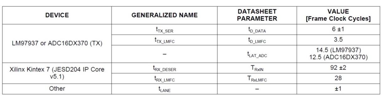
Figure 3. Example link delay parameters for the LM97937 and Kintex 7 FPGA
For RBD set less than K (assume RBD=24), Eq.3 results in the following inequality:

The minimum integer solution is given by N=2 and the resulting the link Latency (Eq.1) and total latency (Eq.2) would be:

Check back in February for my next blog post, which will examine how to choose the RBD value and a method to measure and verify the calculated total latency.
Additional resources:
- Take a deeper dive into JESD204B subclasses and deterministic latency in this training presentation.
- Download our JESD204B white paper for tips on what you need to know when transitioning to JESD204B.
- Read more JESD204B blogs.
- Learn about TI’s JESD204B ADCs, DACs, clocks and tools.
↧
Which is simpler, selecting a Hot-Swap controller or its power MOSFET?
I had company over to the house during the holidays and had to run to the store to pick up a few last minute items. Then I realized how many meanings there are for the three-lettered word “run”. I heard there are 645 meanings for its verb-form alone and growing! Things that appear so simple on the surface can really be quite complex. Consider power MOSFETs having only three pins (gate, source, and drain). When I came back to the office and began working on a new power management hot-swap application, I was reminded after the long break how complex a simple-looking power MOSFET can be, and how selecting a MOSFET for a hot swap application is different than for power conversion.

Figure 1: Simple-looking N-Channel MOSFET
A hot-swap circuit uses a power MOSFET as a series-limiting device and controls start-up inrush and fault currents. During transient and fault events, the MOSFET dissipates power greater than steady-state and can exceed the thermal limits of the MOSFET, so designers must ensure the MOSFET is operated within its Safe Operating Area (SOA). There are many good resources available to help designers choose a suitable MOSET to meet the power dissipation requirements under all of the event areas. Read “Robust Hot Swap Design” to understand the design procedures involved in MOSFET selection. Texas Instruments also offers detailed Excel-based calculators for Hot Swap applications using power limiting that follow the approach outlined in the application note. Here is a link to a design calculator featuring the TPS27420, a 2.5V to 18V hot swap controller with current monitoring. Click here for a complete list of hot swap and e-fuse calculators. A good power MOSFET companion to consider for the TPS27420 is the new 30V CSD17570Q5B in 5x6mm SON package. This MOSFET features the industry’s lowest on-resistance of 0.56 milliohm typical (VGS = 10V) in its package size and is optimized specifically for high-current hot swap applications.
A quick method to check whether a MOSFET can withstand DC or single-pulse currents in hot swap applications is by inspecting the MOSFET SOA curve. These SOA curves typically assume a junction-temperature rise from a 25°C ambient to the rated maximum junction temperature, which is 150°C in this case. However, thermal requirements often need to operate at a higher starting temperature, and data from the graph must be adjusted for a lower temperature rise according to equation 1, where SOAT represents the SOA capability at arbitrary temperature T, SOAJMAX represents the capability at a specific point on the manufacturer’s SOA curves, and TJMAX and TA represent the peak and ambient junction temperatures.
Equation 1: SOAT =SOAJMAX x (TJMAX– T) / TJMAX– TA)
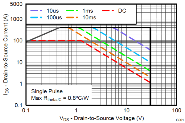
Figure 2: CSD17570Q5B Maximum Safe Operating Area @ 25°C
As an example, the SOA curve shows that the CSD17570Q5B can withstand 15A (or 180W) under the conditions of 12V maximum input with a 1ms pulse at 25°C. When the MOSFET operating junction temperature is 79°C, for example, the power capability is de-rated to 102W = 180W * (150-79) / (150 – 25).
Short one-syllable words appear to be simple but can have complex meanings – that must be why they are used so much in Top 40 song lyrics. Integrated circuits with low pin count can be complex, too. So I vote for the power MOSFET.
↧
Bluetooth Smart in industrial
Have you ever heard of Bluetooth® Smart? It’s the latest addition to the Bluetooth Specification and it uses Bluetooth low energy technology to enable the Internet of Things (IoT) for products that operate on small coin cells for years. How is that possible you may ask? Bluetooth low energy was designed to be low power, only waking up from time to time to transmit small amounts of data with rather high latency in a range that covers up to a couple of meters. Perfect for sensors! That’s how it began in 2010.

It took a year or two until the first products showed up on the market in the form of heart rate belts and smart watches. Then a smartphone came into the picture, Apple iPhone 4S. It was the first phone on the market to support Bluetooth low energy and the market took off. The fact that everyone carrying a smartphone, could connect to all kinds of products in a low power manner was something new. Suddenly, everyone wanted their product to be connected to a smartphone.
As a natural progression came the talk about Internet of Things and cloud connectivity so your smartphone can connect to any-thing and so allowing any-thing to connect to the Internet (read cloud). With this dramatic change, firmware updates could be pushed to products out in the field, smartphones could control helicopter toys and wireless add-ons can replace wires in weird places.
We are at this point closing in on 2015 and all of a sudden, manufacturers are now using Bluetooth Smart (which is becoming the more common name for Bluetooth low energy) for longer-range communication, high throughput transfers and tough ISM applications as well. This is not at all what Bluetooth low energy was designed for. However, Bluetooth low energy is now advancing into high quality industrial applications; replacing whatever has been used for ages, or at least a very long time.
It’s time for a revolution, time for Bluetooth Smart to show its worth in new places. Bluetooth Smart is emerging into unexplored new market segments from hardcore industrial applications and fancy home appliances to trendy beaco-systems [sic].
There are already deployed solutions for use cases including both wired and wireless technologies that can be replaced by Bluetooth Smart. As Bluetooth Smart is evolving and adapting to these new use cases, one might be afraid that there might be a “war” between standards coming. I like to think about it more of an evolution, where the survival of the fittest applies. The future will behold which technology is suitable for what.
However, we can already elaborate on some applications that might be impacted. Take lighting as an example, where ZigBee is dominating the marked with smart bulbs connected in a network to a Wi-Fi gateway. Bluetooth Smart can do star topologies as of now, with a central or smartphone controlling multiple light bulbs. However, ZigBee operates in a mesh network topology which means that information can be routed through nodes and range can be extended beyond the gateway limitation. Bluetooth Mesh is something that could address this in the future as well, if it’s designed in an energy efficient way (i.e. not using flooding etc.) and the security is robust including the complete solution for that matter. But what about the already deployed ZigBee solutions, will those be redundant? Well, not necessarily. What if one node in the ZigBee network adds Bluetooth Smart? Or the gateway includes a Bluetooth Smart interface.
There are other use cases; i.e. Machine to Machine (M2M), cable replacements, asset tracking and automation control that can benefit from Bluetooth Smart in the industrial setting. There are already multiple connectivity technologies with a foothold in the industrial space including Ethernet, ZigBee, Wi-Fi, Sub-1 GHz etc. and Bluetooth Smart can easily complement these technologies. What is needed is a focus on streamlining a set of technologies to define a wireless super-set similar to the useful Swiss army knife.
Why is Bluetooth Smart a good fit for industrial applications? Read the 6-part blog series on ECN Magazine that covers the industrial applications mentioned above and allow me to enlighten you.
- Why Bluetooth Smart is perfect for M2M
- Connecting machinery to the IoT
- How to use Bluetooth Smart in industrial lighting
- How you can replace wires with Bluetooth Smart
- Why Beacon is the next big thing in wireless
- The key to using Bluetooth Smart in asset tracking
↧
5 technology trends to watch in 2015
As we kick off 2015, it’s important that we take time to assess and anticipate the technical challenges and breakthrough innovations the new year will bring. Having met with a number of technologists across our ecosystem of strategic customers, university partners and TI’s product lines in 2014, I would like to highlight important technology trends where TI can play a strategic role. These technology trends are fueling a diverse set of markets including automotive and industrial, in which engineers across TI can address unique semiconductor challenges and advance technology and the way we live.

Top five technology trends for 2015:
1- Internet of industrial things:
While the business model for Internet of Things in consumer applications is still evolving, many industrial enterprises have embarked on adopting large scale connectivity of sensors, machines and devices along with data analytics. The key enabling technologies are sensors, connectivity, efficient energy management, and ultra-low power analog front-end and embedded processors. The proliferation of integrated MEMS sensors over the last few years has largely been driven by mobile devices. In contrast, industrial enterprises have been utilizing expensive high-performance sensors for safety, quality, and efficiency of complex industrial systems. With the improvement of embedded sensors’ performance, deployment of larger sensor networks in industrial, robotics, automotive, commercial and residential automation applications are ramping up. Many diagnostic and prognostic applications in complex industrial plants also can benefit from large deployment of networked sensors. Industrial connectivity will adopt large scale machine-to-machine communication sooner than expected; and industrial and automotive networking will increasingly adopt all IP Ethernet extensively as it becomes more secure and deterministic. Other enabling technologies such as isolation and Electromagnetics Interference (EMI) robust circuits and systems, including low power wireless connectivity, will be instrumental. With these developments taking hold quickly, the Internet of industrial things is about to become a reality.
TI’s product portfolio and innovations include most key technologies required in industrial wireless or wired networks including highly-differentiated isolated interfaces for industrial sensing and measurement, integrated sensors with smart analog frontend, ultra-low power wireless links and embedded processor intelligent power management and many other high precision analog frontends.
2- Semi-autonomous vehicles (cars, robots, drones):
Intelligent vehicles are ready for prime time. Many advances in sensing and processing capabilities that have previously been available in expensive military and scientific platforms are becoming commonplace thanks to exponential advances in semiconductor technology. Advanced driver assistance systems come equipped with a dozen HD cameras, radars, ultrasonic sensors, and subsequently Lidar – providing unprecedented safety and convenience and paving the way toward a further automated driving experience. Drones, which until recently have been novelties in military and entertainment applications have become a commercial instrument in many growing new applications such as security, metrology, and agricultural applications. Robotic applications so far have been mostly in industrial factory floors for highly repetitive, well controlled tasks – isolated from human interaction. However, deployment of robots in healthcare facilities, assembly lines for consumer products and warehouses are among examples which demand smaller and lighter yet highly intelligent robots.
TI’s strong portfolio and new innovations in motor drives, sensors, and battery management are well positioned to play a critical role in the new generation of highly intelligent autonomous vehicles.
3- Small radios: The next big push in communications infrastructure
Today, more than two thirds of the 1 billion terabytes of digital universe data is used and produced by mobile device users. In 2014, the increasing demand for mobile data applications accelerated deployment of 4G LTE networks. However, growth of mobile data has outpaced capacity of macro base stations. Therefore many infrastructure manufacturers and operators have been working on smaller radios with less than 1 watt transmit power and a large number of antenna (massive MIMO) offering both LTE and Wi-Fi capabilities to complement macro base stations. Within the next two years, deployment of lighter radios in hot spots and indoor environments will most likely accelerate and pave the way for massive and heterogeneous radio coverage promised by 5G standard, which is still being defined. Light radios are supposed to be low cost, easy to install and low power.
Technologies such as Power over Ethernet, efficient power amplifiers, high performance processors and integrated radio are among critical IP blocks for future light radios.
4- Smart power and high voltage:
Power management continues to be one of the fastest-growing opportunities within the semiconductor industry. More applications are relying on intelligent power management for efficient generation, distribution, and consumption. Many offline applications including chargers for consumer products have extensive intelligent power management that allow a plugged-in device to communicate its energy needs with a power supply to improve efficiency. Also, power management in servers and data centers are evolving to offer higher efficiency in diverse and highly dynamic load conditions.
Demand for intelligent drivers for high voltage devices ranging from motor drivers, fast chargers, hybrid vehicles, AC/DC line power converters and semiconductor content is growing. Also, new devices such as GaN and SiC are maturing to play a key role in high voltage applications.
5- Isolation key to communications in high-voltage environments:
Isolation technology is increasingly critical for many industrial, automotive, medical and offline applications to provide protection, noise immunity and reliable performance. Gate drivers for high-voltage devices, industrial measurement and monitoring and Industrial Ethernet are among many applications for this technology. The trend toward transferring higher data rates of several hundreds of megabits/s and more across isolation barriers with high efficiency and robustness against high voltage surges is increasingly common in many industrial applications. Also, transferring data and power across isolation barriers is finding applications in gate drivers and industrial sensors.
TI has many new isolation technology offerings and is in development for higher data rate digital isolation with high efficiency.
As a technologist, I am excited about the inventions we are creating in the product lines and within Kilby Labs to answer the demands for these top five trends. I find inspiration and energy knowing that TI has innovators actively working on the technologies today and dreaming big about the breakthroughs that will define the next big trends. Throughout the year in my quarterly columns, I will dig deeper into the above trends. Let’s keep our eyes on these trends and how we can make a stronger impact for TI.
↧
↧
It is not just a PFC controller, it is also a power meter
Real-time energy consumption measurement, including input real power, input RMS voltage and input RMS current measurement for off-line power supplies, is becoming more important nowadays. These measurements could be used to adjust power delivery and ...(read more)![]()
↧
Consumer electronics benefit from analog technology
As we look back on another CES in Las Vegas, it continues to amaze me how much of these consumer electronics contain large amounts of analog. Without the analog functions, consumers would have no idea how much talk time is left in their cell phones, be able to listen to music, take fantastic photos or many other common functions of today’s consumer devices. I guess I’m a bit biased (being an analog guy), and I do recognize the extreme value provided by processors and other digital components, but without the ability to move between the real world and the digital domain, many consumer devices wouldn’t exist.
One area that remains squarely in the analog domain is sensors – the bridge between our physical world and the digital engines that drive these devices. Just about every consumer device has a sensor of some sort, from simple temperature sensors to elaborate multi-sensor systems utilizing sensor fusion to augment reality.
One new breed of sensor that is finding its way into personal electronics is inductive sensing. Inductive sensing has been used in industrial control for years, but with fully integrated solutions, such as the LDC1000, consumer products like cameras, domestic robots and more can greatly benefit from accurate positioning and proximity measurements. A good example of this is an auto-focus lens. Using inductive sensing as a positioning sensor is extremely simple and accurate – so the processor always knows what the current setting is on the lens.
Other sensors can be extremely beneficial for the healthcare sector. There are a number of new personal fitness and home health monitors that utilize acceleration to measure steps and activity, as well as skin resistance and pulse oximetry to measure sweat levels and blood oxygen content. Check out this video on the heath/fitness area at CES.
Devices like the AFE4400 use a simple photodiode and a couple of LEDs to create an entire analog front-end for measuring blood oxygen content as well as pulse rate – all in a tiny package taking up little more space than the bottom of a pencil eraser. These devices are very low power, allowing them to be used in portable applications ranging from in-home medical monitoring to wearable fitness devices. If you are anything like me, having digital personal trainers bugging you to work out is helping to keep those new year’s resolutions!

Personal electronics like smart phones, DVD players and HDTVs all rely on audio amplifiers. Their function has evolved to be extremely efficient using switched-mode amplifiers that use very little power, but provide excellent fidelity. Highly integrated devices such as the TAS5760LD provide a complete solution that converts a digital audio stream (via an I2S interface) directly to speakers. It even has a sophisticated headphone driver for consumers who want to listen in private – all this in a tiny 48-pin TSSOP package.

The future of consumer analog is extremely bright with new sensor technology and highly integrated, low-power analog chips, enabling all kinds of new devices. So next year when you’re walking around CES or simply reading the reviews of all the new gadgets, remember that most of them would not be possible without the analog. Till next time…
↧
Delta Sigma ADC Basics: Understanding the delta-sigma modulator
The delta-sigma (ΔΣ) analog-to-digital converter (ADC) is a mysterious construct to many engineers, shrouded in mathematical descriptions and defying clear explanations. This complexity can deter circuit designers from using this ADC topology and taking advantage of its many benefits. These converters are used in a wide variety of applications, including weigh scales, temperature measurements and seismic monitors for their high resolution capabilities and circuit integration. Let’s remove the shroud of mystery with an introduction from a practical point of view.(read more)![]()
↧