Quantcast
Channel: TI E2E support forums
Viewing all 4543 articles
Browse latest View live

4 ways we’re investing $6.2 million in STEM education

$
0
0

Garland Independent School District is one of several to benefit from funding to improve AP STEM coursework.

STEM skills are survival skills for students today. That’s why we are committed to improving STEM education by arming teachers and students with the resources they need to succeed.

TI and the TI Foundation have committed $6.2 million in 2017 to improve K-12 science, technology, engineering and math (STEM) education across the United States. Here are four examples of how our philanthropic investments drive STEM education:

1. Funding Advanced Placement® Strategies programs in North Texas and California’s Bay Area

The TI Foundation continues to invest in the National Math and Science Initiative (NMSI) Advanced Placement (AP) Strategies program in three North Texas school districts, and it recently expanded its investment to two districts in California’s Bay Area. The aim is to expand access to rigorous STEM coursework, especially among traditionally under-represented students in STEM. Students who master AP coursework are three times more likely to graduate from college[i]. That’s a statistic we can get behind.

2. $5.3 million – 85 percent of our grant funding – is going toward STEM teacher effectiveness and retention

Teachers are our best STEM champions, and the work they do is essential to challenging young minds. That’s why 85 percent of our 2017 grants, $5.3 million, will go toward recruiting, developing and retaining top teachers. The number of U.S. jobs in STEM is growing an estimated three times faster than non-STEM jobs, with a projected 9 million STEM jobs needing to be filled by 2022[ii]. Teachers will play a key role in shifting attitudes and achievements in STEM, and we are helping them reduce the STEM skills gap.

Recent Lancaster ISD graduate Trevor Johnson (right) learned crucial STEM skills in Lancaster’s innovative STEM district model. 3. Funding a new TI Innovation Center for students to receive hands-on STEM experience

The TI Innovation Center will be a stand-alone building located at the Girl Scouts of Northeast Texas STEM Center of Excellence south of Dallas. Scheduled for completion in the spring of 2018, the center will offer STEM programs to 24,000 students over the next two years. The center will also be the home of Girl Scouts robotics teams and small groups that need a safe working space for ongoing projects. An outdoor space will be used by Girl Scouts, students, volunteers, parents and staff members to gather and celebrate STEM accomplishments. Additionally, students from area school districts will be able to utilize the camp for field trips, thus broadening the reach of the program.

Girl Scouts in northeast Texas grow STEM skills through hands-on learning. 4. Helping students apply their passion and improve their chances of STEM success with robotics competitions

Research[iii] shows that students involved in robotics are:

  • More likely to take challenging math and science courses
  • More interested in engineering majors
  • More likely to pursue STEM careers

That’s why we expanded our investments in 2017 to middle school and high school robotics competitions, which is a proven way to increase STEM engagement among participating students. Robotics mentorship and volunteerism isn’t just for engineers, and it’s a great way to make a difference in STEM one robotics team at a time. Explore how you can get involved in a robotics program.


Robotics competitions are an impactful way to get kids interested in STEM. Our commitment to education dates to our company’s inception and remains our highest priority for employee volunteerism and giving. For more information, read about our:


[i]
Based on data from the College Board

[ii] Bureau of Labor Statistics, Occupational Outlook Quarterly, STEM 101: Intro to tomorrow’s jobs.

[iii] FIRST Longitudinal Study: Findings at 36 Month Follow-Up (Year 4 Report)


Design of a camera-friendly, wide-color-gamut, color-tunable RGBW LED light source – part 2

$
0
0
In part 1 of this series, we discussed a few challenges associated with a color-tunable, dimmable light-emitting diode (LED) light source and the various advantages and disadvantages of dimming methods such as analog, pulse-width modulation (PWM) and...(read more)

Extra tricks to increase battery life

$
0
0

In my previous blog post, “Power topology choices for power-hungry devices,” I discussed power topology choices to help conserve battery life. Today, I want to discuss other ways to extend battery life for power-hungry designs, including different software improvements and device options.

Depending on the end-equipment characteristics, software can make or break your battery-life expectations. Wirelessly connected devices can improve their battery life by going into standby for longer periods and reporting data less often. Take a sensor-to-cloud Sub-1GHz device, for example. Environmental data such as temperature, humidity and air-purity level do not change very quickly, so a reporting interval of every 30 or 60 minutes would be sufficient. During standby, the sensors could be asleep; only the radio may have to wake up at a quicker interval period to check back into the gateway and see if the user requested fresh data.

Some end equipment has tighter restraints and cannot sleep. With smoke detectors or security devices, for example, detected smoke or breaking glass are critical events that must be reported immediately. There are a couple of tricks for improving battery life via software changes in these applications. To improve battery life, you can decrease the wireless transmit power if the install location is relatively close to the gateway. Another trick is to have the critical sensor always on while the wireless microcontroller (MCU) sleeps, waiting for an event to occur. The sensor wakes up the MCU to send out a critical event message.

Choosing the right low-power device for your application is another way to improve battery life, but with so many devices out there, it can be hard to find the right one. I want to highlight two devices that are useful in the sensor-to-cloud ecosystem. The first is the LPV802 nanopower dual operational amplifier (op amp), which enables always-on very-low-power motion sensing in our Low-Power Wireless PIR Motion Detector ReferenceDesign Enabling Sensor-to-Cloud Networks. There are many uses for op amps, but this device is also great for smoke detectors and any application where low power is a priority.

Figure 1: Wireless passive infrared (PIR) motion detector reference design block diagram

The second device that may be of interest is the DRV8833 dual-H bridge motor driver, with low-power sleep and the ability to drive two DC motors or one stepper motor. The adjustable current-limiting circuit is another nice feature of this device. You can extend battery life by avoiding unnecessary motor current from a stalled motor or other fault. Smart electronic locks, damper and actuator systems, and any small-motor applications can benefit from a low-power current-limiting motor driver.

Figure 2: DRV8833 (U3) featured on the smart damper reference design board

Texas Instruments has a couple of reference designs that use the DRV8833 motor driver. The Smart Lock Reference Design Enabling 5+ Years Battery Life on 4x AA Batteriesand the Smart Damper Control Reference Design with Pressure, Humidity, and Temperature Sensing both demonstrate the implementation of a motor-control device into a smart connected design.

I hope that some of these tips will help you achieve longer battery life in your designs. Take a look at the various reference designs I’ve mentioned here, as well as the others available on TI.com.

Additional resources:

The seat remembers: Brushed DC motor ripple counting drives innovation in full-featured memory seats

$
0
0

My parents have an SUV that they share between them. When I go home, I might also use their car to visit old friends or run errands. When all three of us are using the same car, we each have to adjust the driver’s seat height, the distance from the steering wheel and the pedals, the steering wheel height, the angle of the chair back, and the angle of the rearview and side mirrors.

Many high-end luxury automobiles have full-featured memory seats and mirrors, where drivers create their own seat “profile” with their preferred angle and height adjustments. With this feature, my parents could save time by not having to readjust the seat and mirrors.

As my colleague Clark Kinnaird discussed in his blog post, “Putting innovation in the driver’s seat,” small brushed DC motors are controlling more and more axes of seat adjustment. Existing technology to measure these seats uses magnetic Hall-Effect sensors attached to the body of the DC motor. Magnetic poles rotate in the motor shaft and provide a field for sensor capture. Multiple sensors can measure the speed and total number of motor rotations and subrotations. The number of motor rotations can be inferred and directly translated into the total distance moved by the seat for that particular axis and saved on the memory seat control module’s microprocessor.

Measuring position

Positional memory and motor speed are not only popular for car seats. Many small-motor automotive applications – including power windows, sliding doors and lift gates – can use information about the speed of the motor to determine stall conditions for pinch detection and optimize motor speed for efficiency with pulse-width modulation (PWM) control. Side mirrors can adjust based on different user conditions, such as changing angles to a set position to give drivers a better view when backing the car into a parking spot. Small motors are everywhere in automobiles, and a simple positional memory solution provides a wide array of convenient features.

There is growing interest in determining motor position and rotational speed without the need for sensors; in some cases redundancy in sensing helps avoid mechanical and electrical failures in memory seats. As small motors control more axes of seat position, there is a need for more Hall-Effect sense elements mounted to the motors, more Hall-Effect sensing integrated circuits (ICs) and more harness wiring to drive the motors and capture sensor data.

Using motor current ripple to measure position

Over the years, researchhas shown methods for capturing brushed DC motor speed and rotational position by measuring the total current flowing through the motor and counting the current ripples generated by the motor’s back-electromotive force (back-EMF). This back-EMF is proportional to the motor speed and generated by the induction of magnetic energy onto the motor commutator poles. The DC motor armature voltage and sinusoidal back-EMF cause the total current flowing through the motor to have a sinusoidal waveform.

Equation 1 expresses the total current flowing through a motor as:

where Varm and Rarm are the voltage applied to the motor armature and the resistive load seen on the armature.

Equation 2 expands VBEMF to be represented by the frequency of the motor as:

where Ke is a motor-specific machine constant and ωr is the rotor speed.

Back-EMF will be applied to every coiled commutator pole, and every shifting of a coil within the magnetic field causes the wire to conduct and create a ripple.

As the motor is turning, the motor brushes cause a short between adjacent commutator poles. This short lowers the effective armature resistance, increasing the total current flow, as seen in Figure 1. Every commutator pole subrotation will cause this effect and add to the current ripple.

Figure 1: Impedance changes that occur due to motor rotation

Effective ripple counting

Now that you understand where motor ripple comes from, you must come up with an effective way to actually measure it. Unfortunately, it’s not as simple as just using a comparator to translate the periodic ripple signal into a general-purpose input/output (GPIO) trigger for a microcontroller. Besides the AC component signal that you need to measure, there is a widely varying common-mode DC component that makes signal biasing and comparator threshold configuration difficult.

The DC level of the signal depends on the motor and changes depending on load. As the load increases, the amount of torque necessary to move the load increases. A larger torque leads to slower motor speeds, and as you can see in Equation 1, will directly change the total DC current. This effectively creates a constantly changing DC bias point for your ripple signal based on the load.

In other applications with biasing issues, you could remedy this with a simple DC decoupling capacitor in the signal path. With correct filtering, you can remove the DC point from the output of a current-sense amplifier, while a simple resistor divider can reconfigure the bias point for optimal signal swing for the comparator stage.

For a ripple counter application, there is another issue at hand. Upon motor startup, there is a very large current spike due to the initial energy needed to fight friction and the momentum necessary to get the motor turning. Motor ripples are typically around 100 to 1000Hz, so the size of the decoupling RC filter becomes fairly large to block DC and pass the ripple signal. With the necessary RC filter size, the time constant also increases. The current spike transient is fast and large enough to not look like a DC signal for a DC-blocking capacitor.

Creative circuitry has led to the development of an innovative way to measure motor ripples while also avoiding complexity in digital signal processing. Figure 2 shows how to effectively translate the initial current measurement with the large transient spike (yellow) into a very easily measured signal for a microcontroller (purple). More details on how to achieve this can be found in the Brushed-Motor Ripple Counter Reference Design

Figure 2: Translating motor current ripple (yellow) into countable signal (purple)

Ripple counting provides a new approach for existing technologies to provide a more comfortable and convenient driving experience. As memory seats continue to expand beyond luxury vehicles, I can see my family using a car with these much-appreciated memory features. Concepts like DC motor ripple counting will help us get there.

Additional resources

Debugging an integrated ADC in a microcontroller using an oscilloscope

$
0
0

You probably don’t reach for an oscilloscope first when debugging an analog-to-digital converter (ADC) integrated into a microcontroller (MCU). But an oscilloscope can help you make sure that the ADC operates as expected. In this blog post, I’ll use the C2000™ Piccolo™ F28027 MCU as an example to show you how.

The precise timing of the ADC is important, especially for closed-loop control systems such as digital power supplies or motor-control applications. In theory, the task is very simple – use the data sheet to configure the ADC according to the system requirements. However, peripherals integrated into MCUs are more and more complex and developers have to be careful readers and not misinterpret the data sheet.

An operational amplifier (Figure 1a) or a resistor divider (Figure 1b) typically drives the input of the ADC. A simplified model of the ADC input has switch resistance (RON), a sample-and-hold capacitor (CH) and parasitic input capacitance (CP). During the sampling period, when the switch (SW) conducts, in-rush current flows through the ADCIN pin in order to charge CH to the input voltage level. This results in a voltage drop on the ADCIN pin due to the current-limiting output impedance of the signal source.

It is a good engineering habit to add a charge bucket filter (R1, C1). The capacitor in the bucket filter acts as a charge reservoir for CH and helps to reduce the voltage drop on the ADCIN pin during the sampling process to a reasonable level (typically 5% of the reference voltage). This filter has a cut-off frequency way above the sampling frequency and is not intended to serve as the anti-aliasing filter. (For more details about charge bucket filter design procedures, see the 16-Bit 1-MSPS Data Acquisition Reference Design for Single-Ended Multiplexed Applications.)

 Figure 1: TMS320F28027 ADC input driven by an operational amplifier (a); and a resistor divider (b)

Figure 2 shows how you can benefit from the usually unwanted effect of voltage drop during the analog-to-digital conversion. The Bidirectional DC/DC Converter Reference Design for 12-V/48-V Automotive Systems uses a C2000 MCU for the voltage feedback loop. The application requires precise control-loop timing including the analog-to-digital conversion. The ADC in the MCU enables automatic sequential sampling of multiple channels, where each channel can have different sample-and-hold time or priority. This results in a complex configuration of multiple registers, which is not trivial.

Figure 2 shows the configuration of the ADC for the bidirectional reference design, with three channels (ADCINA1, ADCINA3, and ADCINB7) sampled sequentially. The clock source for the ADC runs at 25MHz, which corresponds to 40ns per cycle. The sample-and-hold time (tADC_SH) is set to 12 cycles (480ns) and the conversion time (tADC_CONV) is fixed to 13 cycles (520ns); therefore, the complete conversion takes 1µs per channel. Each channel is sampled every 3µs.

 Figure 2: Analog-to digital conversion timing for the bidirectional DC/DC converter reference design

In the reference design, the TLV2272-Q1 operational amplifier drives the ADCINA1 and ADCINA3 inputs (as shown in Figure 1a), whereas a resistor-capacitor (RC) network drives the ADCINB7 input (as shown in Figure 1b). In order to verify the configuration, C1 is removed from all three channels (the first version of the reference design did not implement a bucket filter for ADCINA1 and ADCINA3).

Figure 3 shows ADCINA1, ADCINA3 and ADCINA7 waveforms measured with a Tektronix TDS5054B oscilloscope and Tektronix P5050 low-cost 10X (typically 10MΩ/11.1pF) passive probe. The oscilloscope is set to high-resolution mode. All channels are AC-coupled and the bandwidth is limited to 200MHz.

 Figure 3: ADCINA1 (channel 2), ADCINA3 (channel 1) and ADCINA7 (channel 3) waveforms in the bidirectional reference design

Signal peaks clearly indicate the tADC_SH and tADC_CONV period on every individual channel. Even the end of the analog-to-digital conversion is visible when the sample-and-hold circuit reconnects to the consecutive analog channel. The positive character of the peaks implies that the signal voltage level of the foregoing channel was higher and CH discharges back to the circuit. The absolute value and shape of the peaks are not relevant because the oscilloscope probe significantly affects the overall capacitance on the ADCIN pin. In order to obtain an accurate voltage level, you must use an active oscilloscope probe with minimal input capacitance.

Success story

Five minutes in the lab helped identify the bug shown in Figure 4. According to F28027 errata, the first ADC sample at the beginning of every series may be corrupted. One solution is to add an extra conversion in the series and discard the first result. Another solution is to change the timing of the ADC by disabling overlap mode and reducing the ADC clock to a maximum of 30MHz. I initially attempted the first solution, but decided to use the second solution. However, I did not change my source code properly and the extra conversion remained in the code flow. After removing the extra line of code, the ADC operates identically to Figure 2.

 Figure 4: Unexpected conversion every 10 cycles

Conclusion

The technique I’ve laid out here uses inexpensive equipment and gets you one step further in designing reliable, high-performance and robust applications. For additional information, download the code snippet I used for this example below (text file).

Designing with PIR motion detectors: part 1

$
0
0
Imagine waking up in the middle of the night to find that all of your motion-sensitive lights have suddenly turned on. Now you’re stuck wondering whether there is a stranger in your home or if Fluffy the dog simply triggered the lights while on...(read more)

6 hidden benefits of a Brushless Driver

Using mmWave technology to enable sense and avoidance in drones

$
0
0
Despite the great advantages to be gained from the use of drones in civil applications, such as weather forecasting, package delivery and 3-D mapping, the drone industry faces a dual challenge: the demand for both safer flights and lower prices. Most...(read more)

How to correctly layout a 40A power supply: copper, vias and loop path

$
0
0

The demand for energy has gone up significantly but overall solution size continues to shrink.  To adapt, you can decrease the size of a buck converter but it must still be able to handle the increasing power consumption in the electronic system. Optimizing the layout to increase the efficiency of the buck converter will result in less electricity needed to power the system. 

Many electronic systems require several buck converters to supply power to different rails.   Some systems may need two converters or more to power a single rail with a high current demand.  The challenge of designing a smaller buck converter to satisfy this demand becomes a daunting task, but it is possible.   

New technologies and processes are now in place that enable integrated circuit (IC) designers to design buck converters that can handle up to 40A for a single output.  However, this capability introduces other issues.  One is the printed circuit board (PCB) layout.  You can design the best buck converter and power stage with space constraints in mind, but if you fail to lay out the PCB correctly, all will be lost. 

With the current at 40A per output, PCB layout is crucial in regards to heat dissipation and efficiency.  If you don’t optimize the board design, the DC loss at 40A can increase greatly due to the higher resistance of the copper-poured area.  So in this post, I’ll explain the importance of the copper-poured area, via size and quantity, and current loop path on a multi-layer circuit board.

Copper poured area

If you know the cross-sectional area of the copper (thickness × width), length and resistivity, you can calculate the resistance of the copper trace, copper plane or copper pour.  With this data, you can size the copper to optimize the PCB’s thermal, efficiency and signal-integrity performance.  A multi-layer board with multiple buried cooper planes connected with vias to the top layer or bottom layer can also help disperse the heat away from the IC. Figure #1 shows the difference in efficiency between switch-node areas.  The modified switch-node area is larger than the original, which decreases the DC loss. 

Figure 1: Modified switch node area showing a size increase vs. original switch node area

Via size and quantity

Vias make up series-resistance elements when they connect two traces or plane together.  Generally, multiple vias in parallel will reduce the effective resistance.  Just like the flat copper area and thickness, vias have a finite resistance. So you must optimize the vias’ quantity and size to optimize the thermal performance and efficiency of a converter design.

Figures #2 and #3 represent two PCBs with identical set-ups and layouts.  The only difference is the amount of vias on the thermal pad of the IC.

Figure #2: PCB with 11 vias under the thermal pad

*S2 (Site 2): Location of the integrate FET on the IC


Figure #3: PCB with 35 vias under the thermal pad         

Current loop path

You also need to optimize the path of the current loop between each alternate state of operation of the high-side field-effect transistor (FET) and the low-side FET in the buck converter.  Your optimization should include the distance and current-carrying capability of the loop.  Properly planned designs of the IC pin-outs also become a factor in the PCB layout process.  You should minimize the current-loop area as much as possible. 

As semiconductor technologies and processes continue to evolve, we are packing more silicon into the same package to enable higher current rated converter designs. Consider for example, the new 40A SWIFT™ TPS543C20 synchronous step-down converter with adaptive internal compensation and integrated NexFET™ MOSFETs.  However, the fundamental question remains of how to optimize the design so that we don’t compromise thermal performance and efficiency. Hopefully this blog helps you correctly create a smaller-sized, true 40A power supply design.


Diversity fuels innovation and 6 other career lessons our interns learned this summer

$
0
0

Interns
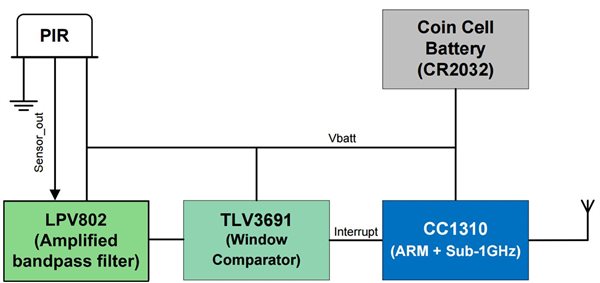
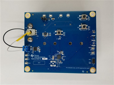
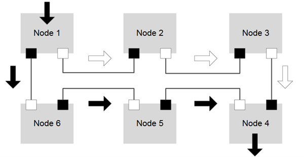
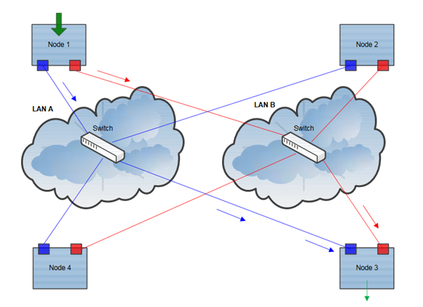
Our student interns are creative and driven, so when a group of them were challenged to develop innovative designs, three applied smart features to a table game that’s a fixture in many college dorms.


Alex Edwards, Rahul Hingorani and Kyle Daruwalla lifted the top of a foosball table, exposed the game’s hidden workings, and plugged in some infrared sensors and a BeagleBone development board to automate scoring and manage tournaments digitally. They tackled this project in addition to their regular responsibilities as interns.


“This is a great learning environment,” said Alex, who spent the summer working on a digital logic design before heading back to Oklahoma Christian University. “It’s a fun place to apply engineering knowledge. You have to come prepared to learn and embrace the fact that you don’t know everything you need to know.”


They were among more than 500 interns who worked at our U.S. campuses over the summer. The interns didn’t shadow. They didn’t make copies. They dove into challenging projects right away and found creative solutions to technical challenges.


We asked a handful of our interns what they learned this summer. Here’s what they had to say:


Diverse teams can create amazing things1. Diverse teams can create amazing things

“My biggest takeaway was that nothing carries a team forward better than diversity,” said Grayson Noah, who spent the summer working in a product engineering group. “Different perspectives, skill sets and personalities all work together to do something amazing. When I started my internship, I was thrown into one of the busiest parts of the product cycle and treated as a full member of my team. My team and the work enriched my experience and skills immensely.”

Stay curious and confident2. Stay curious and confident
“My projects gave me the opportunity to test myself, my interests and how I like to work,” said Shannon Peifer, who worked a communications and digital marketing intern. “The internship made me more curious about the different areas of marketing and communications. It has made me more confident to ask questions and dive deeper into unfamiliar areas.”

Speak up3. Speak up

“This summer taught me that the work I do, no matter how small it may seem, has the potential to impact the company in a big way,” said Vinessa Burnett, a human resources intern. “And if I speak up about an idea I have, not only will people listen, but people will provide me with the resources and insight to help turn it into reality.”

Teamwork is critical4. Teamwork is critical
“Working in a field as competitive and fast-moving as electronics and integrated circuits requires a huge pool of knowledge,” said Chance Coats, who worked in a product engineering group. “No one could possibly know everything on their own. You need a great group that supports and assists you when you need help. The members of your team bring their experiences and perspectives to everything they do, and leveraging these invaluable resources allows TI to provide some of the best products in the world.”

Jack Sacone5. Push yourself to learn
“Working at TI gave me valuable insights into my field of engineering and the opportunity to work on real products that are at the cutting edge of embedded processing,” said Jack Sacane, a software engineering intern. “This summer pushed me to learn new skills and technologies that aren’t taught in school. Everyone here is an expert at something, and I’m always able to find someone who wants to help.”

Build your knowledge6. Practice hard and soft skills
“I met with people from different teams in Santa Clara and saw a wide range of projects,” said Erick Leal-Castillo, a product engineering intern in California. “I also got to practice new hard skills like automation and soldering, but also soft skills like project management and networking that will help me back at school and in my career.”

Build your knowledge7. Build your knowledge
“Working at a place like TI and working on projects is a completely different experience than being at school,” said Rahul Hingorani, a software development intern. “I’ve figured out how to do well in school, but when I came here I realized I had to build my knowledge and work with other people. This isn’t like doing a project at school. There’s a lot more involved in the process.”


Learn more about internship opportunities at our company.


Unique techniques to increase controller power

$
0
0

The better you understand a tool, the more powerful it becomes.

One example of this is the Tektronix 576 curve tracer.  At first glance, it looks like a machine that only measures a three-terminal bipolar junction transistor (BJT) or field-effect transistor (FET).  That’s how it was advertised, so that’s what I thought until an especially talented product and failure analysis engineer showed me otherwise.  He demonstrated that this machine is really just a precise voltage and current supply with accurate measurements of both, down to the megavolts/nanoampere range.  By dynamically measuring a current-voltage (I-V) curve graphically, this tool is actually one of the most powerful circuit debugging machines in the lab.

At first I was skeptical that an old analog machine with a phosphorous cathode ray tube (CRT) monitor and mechanical switches was capable of supplying over 1kV.  My doubts didn’t last long, though, since there was soon a puzzling failure on a reliability test that we were running for a device in development, with a public announcement approaching.  Using the curve tracer, we were able to track down the root cause to intermittent pin-to-pin shorts of the quad flat no-lead (QFN) package due to board-level issues.  We shared the results with cellphone pictures of the CRT monitor; this old machine, designed for a different purpose, clearly showed the voltage collapsing momentarily as shorts between two pins formed and then fused open.

The same applies to any device used in a circuit, just because it’s advertised to work in one specific case doesn’t mean it will work well elsewhere.  While it may be easy to read the first page of a data sheet and assume that the device can only work in the specific configurations listed, that is not always the case.  One example is the maximum power of the offline converter for TI’s UCC28880 and UCC28881 switchers.  At the beginning of the datasheet a table is provided to help readers understand when which device should be used, as shown with Figure 1.

Figure 1: Power-rating table in the UCC28881 data sheet

While this table implies that 4.5W is the maximum power that this family of devices is capable of supplying when configured as a flyback, this is not necessarily the case.  The maximum power limit comes from the peak current limit (ILIMIT) of the device.  This current reaches its limit at the lowest power level at the minimum input voltage, which is 85V for a design that can support a universal input.  If the input is limited to just low line (i.e. North America, Japan) or high line (i.e. Europe, Asia), the maximum capable power level is actually higher.  While it’s obvious for high line since it has lower input currents for the same power level, low line only input requires a slight modification to the typical schematic.

This is demonstrated with 100V-450VDC, 5W, 80% Efficiency at 1W, Auxiliary Supply Reference Design for AC-DC Power Supplies.  By having a 100V DC input instead of an 85V AC input, the minimum input voltage is higher.  This enables this design with UCC28881 to have a maximum power of 5W, which is above the 4.5W maximum of the table in the data sheet.  This increase cannot continue forever though, since other limitations like thermal capability start to have an impact and can limit the operating range from reaching its theoretical capability.

Techniques like this are not limited to maximum power capability. I’ve compiled a list of reference designs that show other unique ways to bias offline power-supply controllers so that they work in conditions beyond what’s typically advertised.

Applications of Low Voltage Differential Signaling (LVDS) in Multifunction and Industrial Printers

$
0
0

Multifunction and Industrial printers often include a data path where an image must be passed between multiple boards in the system. This creates concerns for designers including noise immunity, electromagnetic interference (EMI), and power consumption over these links. In this post, I’ll take a look at how the different circuit boards in multifunction and industrial printers communicate with each other, with a particular focus on where low-voltage differential signaling (LVDS) is applicable.

Multifunction printers integrate office document management functions into one device. These functions include the ability to email, fax, photocopy, print and scan. There are two types of industrial printers: large format printers, which support a print-roll width of over 18 inches for printing banners, circuit schematics, architectural drawings or other large-format materials; and production printers, which are used for high-speed, high-volume printing of manuals or booklets.

LVDS transmits image data within these printers (from the scanning elements, to a user interface screen, to the printing elements), in addition to transmitting clock and/or control data between boards in the system.

When compared to other communication methods, LVDS provides the following advantages:

  • Noise immunity due to differential signaling.
  • Longer communication distances due to current-mode logic.
  • Low EMI due to having opposite signals on differential lines in a twisted-pair cable.
  • Low power consumption.

Additionally, serialized LVDS signals provide these additional advantages over parallel LVDS:

  • Reduced layers on the printed circuit board (PCB).
  • Reduced cable weight and cost.
  • Additional EMI reduction.
  • No need to worry about skew among parallel lines and clock.

Figure 1 depicts a functional breakdown of a multifunction or industrial printer. Although LVDS functionality is increasingly integrated into field-programmable gate arrays (FPGAs) and application-specific integrated circuits (ASICs), for the purposes of this blog post, I’ll treat all LVDS functionality as discrete. A conceptual data path for a printer begins with a scanned image that passes to the main board for image processing. The image to be printed then passes to a printer control board. Let’s explore the signal chain for image data as it is scanned, manipulated and printed.

Figure 1: Multifunction/Industrial Printer Simplified Block Diagram

The signal chain in a multifunction or industrial printer can be conceptualized into four blocks:

  • Scanner block.
  • Main processing block.
  • Printing block.
  • User interface block.

Scanner block

Figure 2 takes a close look at the scanner block. This block receives image data from the charge-coupled device (CCD), usually through a dedicated analog front-end ASIC, and passes this data to the main processing unit. The scanner block may split into separate automatic document feeder (ADF) and reader control boards, as Figure 2 shows, or combined. Analog front-end ASICs transmit the scanned image data via parallel LVDS to the reader ASIC, or directly to the image processing board. If the design has a separate reader ASIC (as shown in Figure 2), parallel LVDS or SerDes LVDS is used to receive and transmit that image data to the image processing board. The cable length required between the reader control board and the image processing board can be the deciding factor in whether to use parallel or SerDes LVDS, as you can offset the extra cost and engineering work involved with implementing a SerDes solution by reduced cable cost and/or reduced EMI.  TI’s DS92LV2421/DS92LV2422 and DS92LV0421/DS92LV0422 are good example of serializer/deserializer pairs to implement this functionality.


Figure 2: Scanner Block Diagram

Main processing block

The main processing block consists of an image processing board and a main control board. The image processing board contains ASICs/FPGAs that receive the scanned image data sent from the scanner. If the printer is operating as a photocopier, the image data passed to the image processing board is manipulated and sent via LVDS to the printing block. If the image data comes from another source (email, cloud printing, etc.), the image processing board formats the data and passes it via LVDS to the printing block.

As I mentioned, LVDS data may be transmitted via SerDes or parallel LVDS. Cable length is a point of concern; for large format printers, the physical distance between the image processing board and the device control board can be as long as 4m. The use of parallel LVDS over these longer distances might necessitate LVDS devices with low clock skew (<100ps), as well as equalization features to deal with signal loss.  An example of a TI part with this low skew is the SN65LVDS047.

LVDS communication is also used to transmit image data for the user interface to a screen on the front of the printer from the central control board. These transmission distances might approach 2 feet of cable length, and occur via SerDes (shown at the bottom right of Figure 3). Multiple SerDes lanes may transmit this data, with data rates around 1.5Gbps depending on the resolution of the user interface screen.

Figure 3: Main Processing Block Diagram

Printing block

The printing block consists of a device control board and a laser board or inkjet board, depending on the print methods used. The device control board receives the image data to be printed (either via a deserializer or a parallel LVDS receiver) and performs additional functions to change the data into control signals for the laser board or inkjet board. The LVDS link between the device control board and the laser/inkjet board transmits these control signals, along with clock information.  TI’s SN65LVDS389/SN65LVDS388A is an example of a transmitter/receiver pair well-suited for this application.

Figure 4: Printing Block Diagram

User interface block

The user interface block consists of the display screen and any hardware needed to configure the signal for that display. Data sent via serialized LVDS will require a deserializer, and the output of that deserializer will depend on the input format required by the display (RGB or LVDS).  TI’s SN75LVDS83B/SN65LVDS822 is an example of a serializer/deserializer pair that can transmit RGB levels through LVDS and translate back to RGB at the receiving end for a display.

Figure 5: User Interface Block

In summary, LVDS is a preferred method of communication when transmitting high-speed data over longer distances or when there are concerns about EMI, power consumption or cable cost/PCB layer cost.

Leave a comment below if you want to learn more about anything discussed here, or if there is an LVDS topic you would like to see in the future.

Additional resources

Crafty idea: Create a 150V non synchronous buck solution with a lower Vin rated controller

$
0
0

Many applications today require an input-voltage rating beyond the VIN max ratings of many DC-to-DC controllers. Traditional options include using expensive front-end protection or implementing a low-side gate-drive device, which means employing an isolated topology such as a flyback converter. Isolated topologies often require custom magnetics and increase design complexity and cost compared to a nonisolated approach.

But another alternative exists that enables you to resolve the issue by using a simple buck controller with a VIN max less than the system input voltage. How is this possible?

Buck controllers typically derive a bias supply referenced from ground potential (0V) (Figure 1a). The bias supply is derived from the input; therefore, the device needs to withstand the full VIN potential. However, P-channel buck controllers have the gate-drive supply referenced to VIN (Figure 1b), because the gate-drive voltage required to turn on the P-channel metal-oxide semiconductor field-effect transistor (MOSFET) is at VGS below VIN. To turn off the P-channel MOSFET, the gate voltage simply goes to VIN (0V VGS) (Figure 2).

Figure 1: VCC bias generation for N-channel (a); and P-channel controllers (b)


Figure 2: Gate drive for a P-Channel controller

The fact that the nonsynchronous P-channel controller derives its bias supply to drive the P-channel gate in this way is a huge benefit and makes it possible to supply a virtual ground that floats above a 0V potential. For an N-channel high side MOSFET the voltage is derived from a supply that is referenced to ground.  This is charge pumped using a boot capacitor and diode to supply a gate voltage higher than its source potential of VIN.   With a P-channel high side MOSFET, things are a lot simpler.  To turn on the P-channel MOSFET, the gate potential needs to be lower than its source potential of VIN.  Therefore the supply is referenced to VIN only and not VIN and ground as described above.

Floating ground

How can you create a floating ground for the controller? It’s quite simple: by using an emitter follower. Figure 3 shows a basic implementation of such a scheme. The emitter of the P-channel N-channel P-channel (PNP) will sit at a potential that is Vbe (~0.7V) below the Zener diode voltage potential (Vz). In essence, you’re floating the controller to VIN and regulating the reference of the controller to limit the voltage between VIN and the device ground.

Figure 3: Creating a virtual ground using a simple emitter follower scheme

Output-voltage translation

There is one challenge to overcome. Because the controller is sitting on a virtual ground (Vz-Vbe) and generating a step-down output voltage that is referenced to ground (0V) potential, how are you going to translate the output-voltage signal to a feedback voltage (typically between 0.8V and 1.25V) sitting above a virtual ground? Figure 4 illustrates the challenge.

Figure 4: Schematic showing the difference in voltage potential between VOUT (referenced to 0V ground) and the feedback voltage of a controller (referenced to virtual ground)

To close the loop, you can implement Figure 5 by using a couple of matched-pair transistors. One pair sends the feedback signal to VIN; the other matched pair generates a current from VIN to a potential above the virtual ground.

Figure 5: High-level schematic of a nonsynchronous controller and feedback implementation using matched-pair transistors

Putting it all together

The LM5085 is ideal for the application I’ve described because it is a P-channel nonsynchronous controller whose VCC bias supply is referenced to VIN. The LM5085 can withstand input voltages up to 75VIN in traditional applications. For applications with input transient voltages much higher than 75V, consider the solution presented here, specified for an output of 12V.

Starting from the controller feedback voltage of 1.25V and using a current to generate the feedback (Ifb) set to 1mA, calculate the Rfb value using Equation 1:

where Rfb = 1.25k.

Rfb1 sets the reference current for the current mirrors. Once again, with 1mA as the reference current and using Equation 2, calculate Rfb1 to set the output voltage:

where VOUT = 12V, Rfb1 = 11.3k and Vbe is ~0.7V.

With 1mA flowing into Rfb2 and the emitter current being approximately equal to the collect current (Ie~Ic), this sets the reference current Iref2. The loop is closed and the voltage will regulate to the set voltage described.

Output voltage regulation

One possible application this idea is suitable for is when voltage transients are significantly higher  than the absolute maximum of the LM5085. The LM5085 is a constant on-time (COT) controller; as such, its on-time (Ton) is inversely proportional to VIN. However, when clamping the VIN to the LM5085, Ton will no longer adjust with increasing VIN (to the power stage) because the device will have a fixed voltage set by the Zener diode while the Vin to the power stage is increasing. This will cause the frequency to drop as the input voltage to the power stage increases beyond the clamping voltage to the LM5085; the regulation voltage may begin to increase slightly as a result. Therefore, take care to size the ripple-injection voltage using a Type 1 ripple-injection scheme, thus ensuring that the ripple is set within acceptable limits to maintain stability and minimize error on the output from increasing ripple.

Example schematic

Figure 6 shows an example schematic of a 48V supply with an absolute maximum VIN rating of 150V. The example board can deliver 12VOUT at 3A.


Figure 6: A 24V to 150VIN (max)/12VOUT at 3A design using the LM5085

Figure 7 shows an efficiency plot taken from a prototype board, with efficiency (%) vs. load current (A).

Figure 7: Efficiency (%) vs. load current (A) at various input voltages

Figure 8shows the switch-node voltage and inductor ripple current at 150VIN.

Figure 8: Channel 1 switch-node voltage, channel 4 inductor ripple current

Conclusion

You can use a P-channel nonsynchronous buck controller in applications where the input voltage of the system exceeds the maximum input-voltage rating of the device. This application has the benefit of using a lower-cost controller with minimal component count. For design guidance on the power stage of the buck converter, please see the application information in the LM5085 data sheet.


Optimize the emissions performance in your isolated system

$
0
0

“Emissions Impossible”! Emissions are inevitable when it comes to switching circuits. With circuits that have an external transformer for isolated power, you can increase the size of the transformer to proportionately reduce the switching frequency and thereby reduce the switching noise that causes emissions. But you cannot eliminate this noise completely. In my last post, “Small doesn’t mean you compromise performance,” I discussed the benefits of an integrated solution that provides better performance compared to a discrete solution. Including a transformer in the integrated solution has its advantages, but it also puts an additional burden on emissions performance.

Let me elaborate. When integrating the isolation transformer inside the chip, the size and turns of the transformer are minimized so as to keep the die size reasonable. For the same power transfer, this increases the switching frequency, which results in higher emissions. Figure 1 shows how data and power transmission from the left side to the right side happens through the isolation barrier using a high-frequency carrier. The isolating device connects to two sides of the printed circuit board (PCB), forming a dipole antenna. Since the high-frequency carrier is generated and passed through the isolating device, the formed dipole antenna radiates energy. The radiations are perpendicular to the direction of the dipole.

Figure 1: Creation of a dipole in an isolated system

These radiations not only affect the signal integrity of the isolation output but also interfere with adjacent signals and cause data corruption, ultimately leading to system failures in some cases. So it is important to keep the radiations as low as possible. Standards vary depending on applications, but Comité International Spécial des Perturbations Radioélectriques (CISPR) 22 is the most common standard used in industrial applications. TI has used this standard to compare the performance of different solutions.

Figure 2 shows the radiated emissions comparison of TI’s ISOW7841 integrated isolated signal and power solution with a similar device on the market. TI tested both devices on the same evaluation board with identical load conditions. With careful circuit design and clock management, the ISOW7841 passes CISPR Class B standards, while the competitor’s device fails.

Figure 2: Radiated emissions of the ISOW7841 and a competitor’s device at a 5V input and 80mA load

One way to further reduce emissions is by reducing the power-supply voltage. If there is any flexibility between 3.3V or 5V power supplies, using a 3.3V supply reduces the slew rate of DC/DC converters, thereby reducing emissions, as shown in Figure 3.

Another common method of reducing emissions is adding a stitching capacitor between the left and right side of the isolated board. Figure 4 depicts scenarios where the stitching capacitor is present and absent across the isolator. This stitching capacitor may be a physical capacitor added on the board or included in the board design by using the GND and VCC planes of the board to build it internally. The application note, “Low-Emission Designs With ISOW7841 Integrated Signal and Power Isolator,” has more details about stitching capacitor design guidelines.

Figure 4: The ISOW7841 with and without a 30pF stitching capacitance at a 5V input and 80mA load current

Controlling radiated emissions is important to overall system performance, thereby making device selection with low emissions critical. The ISOW7841, with its simple board design changes, enables you to achieve the right emissions performance. If you have questions regarding board schematics or layout reviews, post a question in the TI E2E™ Community Isolation forum.

Additional resources

Six weird ways to design with a brushless-DC driver

$
0
0

There are two absolute truths that I have come to know. First, brushless-DC motor drivers are cool. Everyone loves the thrill of spinning motors, and brushless-DC motors amp up the wow factor by being high speed, high power and high efficiency. Second, engineers like to be creative. Sometimes, they try to get very, very innovative in their solutions to design problems. Sometimes, they may get a little bit too innovative for their own good. In this post I will discuss a few odd, out-of-the-box uses for brushless-DC drivers that I find can be strangely informative to talk about (Figure 1).

Figure 1: A depiction of myself exiting the realms of sanity

1. “Brushless,” you say?

Three-phase drivers are brushless-DC motor drivers … mostly. These devices integrate three integrated half-bridge gate drivers, which are traditionally associated with controlling a brushless-DC motor, but you can use these outputs to drive pretty much whatever kind of load you want. One common thing to do is drive three solenoids or relays using the three half bridges. Or you can drive two brushed-DC motors between the three phases, like the Automotive 2-Axis Power Seat Brushed DC Motor Drive Reference Design, which uses the DRV8305-Q1. Unfortunately, the marketing team was not enthusiastic about the prospect of calling DRV832x “brushless-DC-gate-driver-or-solenoid-driver-or-dual-brushed-DC-motor-driver-or-whatever-you-want-to-drive-we-don’t-really-care.” But, you get the point about how versatile these drivers can be.

2. Look ma, no MCU!

Brushless-DC motors are hard. You often need to deal with a lot of code just to get the darn thing to start spinning. To make life a little less depressing, someone came up with an input mode called 1x PWM. This mode is interesting because you can tie Hall sensor inputs directly back into the driver, and it will spin the motor (see Figure 2). It’s a quick and easy way to spin a sensored brushless-DC motor without much know-how. It’s not the most high-performance solution, but it works. You can read more about 1x PWM mode in the DRV832x datasheet. (You can also take a look at some othergreatparts specifically made to drive brushless-DC motors without a microcontroller [MCU], without Hall sensors and with sinusoidal drive.)

Figure 2: Drop in and spin!

3. Stupid-proofing

If I had a dollar for every board that I had destroyed by plugging in the power backwards, I would be very rich and happy. Instead, all that I have are bleak memories of releasing the “magic smoke” from hundreds of integrated circuits and passive components (why, electrolytic capacitors, why!?). But there is something that you can do to protect your innocent circuits from yourself (Figure 3). You can actually implement reverse-supply protection using a seventh field-effect transistor (FET) controlled by the charge pump included on the brushless-DC driver. This application note, “Backwards Batteries: Protecting Automotive Motor-Drive Systems from Reverse Polarity Conditions,” explains how you would go about protecting your board from yourself.

Figure 3: Every day, thousands of helpless components are injured or killed through improper use; learn what you can do to help at training.ti.com

4. Who needs a supply anyway?

Did you know that you can operate some brushless-DC motor drivers down to 0V? It’s only a slight overstatement, but this device can be operational even if the motor supply suddenly goes away, albeit for a short time. It turns out, if you add just a simple diode in series with the driver supply pin (see Figure 4), the device can stay operational for a transient duration in the event that the supply voltage drops out. This is a nice way to operate the driver through quick battery droops due to high current loads. Not all brushless-DC motor drivers can do this however. Only ones that include separated supply (VM) and protection (VDRAIN) pins can operate off a filtered supply. Prominent examples of supported devices include the DRV832x.

Figure 4: A little diode goes a long way

5. More power, more problems

You can find really low RDS(on) FETs. I mean really, really low. But sometimes, even the lowest of the low is not good enough. For some applications, you need to parallel up FETs to enable 1kW or even higher power to the motors (Figure 5). While this is something that you can do with the many brushless-DC gate drivers, there is a common design pitfall that people stumble into: when you put FETs in parallel, they will not be perfectly matched. This causes the FETs to “ring” against each other, causing oscillations. There is an easy fix, however – just stick a small resistor between the FET gates. You can see an example of a parallel FET design done right on the 18V/1kW, 160A Peak, >98% Efficient, High Power Density Brushless Motor Drive Reference Design.

Figure 5: Sometimes, you need to crank the power up to 11

6. Sense & Sensibility (or a lack thereof)

I may be a little bit inhibited when it comes to common sense, but that’s not the topic of discussion right now. Sense resistors are used in brushless-DC motor drive systems in order to measure the motor current. Normally, a sense or shunt amplifier will gain up the voltage across the sense resistor, and then send that information to the system MCU for processing. (TI has a few good examples of current sense amplifiers.). The DRV8323 and DRV8323R actually have a unique mode of operation where the low-side FET acts as the “sense resistor.” The voltage across the low-side FET is amplified and provided as an output to the MCU. The advantage here would be eliminating the very large sense resistor components. The disadvantage is that the FETs normally have a higher variation on their resistance compared to dedicated sense resistors.

Now that I have reveled in some of the odd things that you can accomplish with a brushless-DC driver, I can sign off happy. Do you have any weird ways that you are using a brushless-DC motor driver? Please share in the comments so that I don’t feel like a complete oddball. Make sure to subscribe to this blog for more information about motor drives.

Additional resources


Sync your multichannel data acquisition systems up to 15GHz

$
0
0
Most advanced systems like digital oscilloscopes (DSOs), phased-array radars and 5G wireless testers require multiple synchronized signal chains that include high-speed (gigasamples per second) analog-to-digital converters (ADCs) and digital-to-analog...(read more)

Self-driving racing cars put processors on the podium

$
0
0

Infinity Racing team’s working prototype.Until recently, the concept of a self-driving car seemed like the stuff of science fiction. But in just a few short years, some of the world’s largest car manufacturers and tech giants from Silicon Valley to Munich are testing various levels of vehicle autonomy. Industry experts predict that the first highly to fully automated vehicles (AVs) will hit the market between 2020 and 2025.


It’s not just on city streets that driverless vehicles are making their presence felt. Earlier this year, visitors to Mobile World Congress in Barcelona were treated to the unveiling of Robocar, an autonomous race car designed to compete in the recently formed Formula E racing series.


Now, students participating in this year’s Formula Student Germany (FSG) competition are designing and building their own driverless race car to be tested on a specially designed circuit in Hockenheim, home of the legendary race track used by the likes of Formula 1.


FSG is part of Formula Society of Automotive Engineers (SAE), a global student engineering design competition based on the concept of a fictional manufacturing company contracting students to develop a Formula-style race car. One goal of Formula Student Germany is to set new trends for the automotive industry. After successfully introducing Formula Student Electric in 2010, the organizers of the competition added a category for autonomous vehicles to this year’s competition.


With a little help from automotive experts at our company, the Technical University of Munich’s (TUM) TUfast team has spent the last 12 months designing and constructing self-driving race cars in their free time and on a restricted budget.


This year, our company has supported the TUfast team by providing technical advice, as well as samples and evaluation modules (EVMs) to support the car’s autonomous system design.


“You can be sure that every printed circuit board module has TI technology, and although we have developed some of our own sensors, they are mostly based on TI parts,” said Tobias Spath, TUfast team leader. 


Formula Students Germany, TUfast team member at competition
Rather than building a new car from scratch, the TUfast team adapted its 2015 electric vehicle entry so that it could operate autonomously. One of the most significant challenges the team faced was to choose from hundreds of sensors and actuators for an existing vehicle without sacrificing too much power.


To help the team manage power consumption, the TUFast team is using a range of technologies from our company, including LMZ31707RVQT SIMPLE SWITCHER® power modules and DCR011205 DC/DC converters.


“We only had about 800W of power to play with in total, so this meant finding creative ways to add the necessary actuators and sensors to the vehicle without overloading the system,” Tobias said. “We encountered a number of challenges along the way, both in terms of space and power. This is where the efficiency of the TI parts we used really helped. So far, the results are promising. We felt an enormous sense of achievement when we got the car to accelerate and break on its own.”


To Infinity and beyond

Another team working with our company this year is Kempten University’s Infinity Racing. The team is comprised of 40 people covering everything from design and marketing to mechanical engineering.


Thorsten Lorenzen, senior field applications engineer for automotive advanced driver assistance systems (ADAS) at our company, supports the students as a technical advisor.


Infinity Racing team with their self-driving prototype.“Kempten is the only university in Germany that has a faculty specifically for ADAS,” Thorsten said. “I became involved with the university about a year ago, devising a course for students covering concepts and principles related to self-driving vehicles. We have an incredibly broad portfolio of technologies that enable semi-autonomous systems, so it has been fantastic to see the students put these technologies to use in their prototype.”


For its car to sense and analyse its environment, Infinity Racing used a combination of camera sensors and GPS technology to plot, log and process the route. Sitting at the heart of the system is the RVP-TDA2x board from D3engineering. Based on our TDA2x advanced vision processor, it enables synchronous acquisition of four FPD-Link III HD data streams for real-time vision processing and analytics. The camera recording the route also uses high-speed data technology from our company.

 
Get your motor running

TUfast recently put its car to the test at the Formula Student Germany competition, racing autonomous vehicles built by student teams from across the world. The team won fifth place overall and took first place in the business plan and third place in autonomous design subcategories.


For Infinity Racing, the past year has been an incredible and rewarding challenge that has resulted in a working prototype.


“We’ve really only scratched the surface in terms of what is possible,” said Kaan Ayhan, electrical architecture driverless student lead. “TI has been a great support throughout, giving us the best possible equipment we needed, as well as workshops to help us use the hardware optimally.”


With the help of our company, automotive developers are able to more quickly and easily design ADAS and semi-autonomous systems. Ultimately, the students hope to bring self-driving cars on the road with TI’s broad portfolio of ADAS technology.


Copyright Formula Students Germany

Inductor-free innovation: low EMI Class-D audio

$
0
0

It would be a mistake to dismiss the ever-present television set as lacking innovation. According to the Consumer Technology Association (CTA), every year more than 200 million TVs are sold worldwide. Although overall the technology is mature, with low growth of 1-2% and dozens of competitors, the most innovative TVs, like 4K TVs, will grow at an amazing 55% year over year for a total of 82 million units in 2017.

Higher-resolution TVs push the innovation frontier even further; however, innovation can take many forms like lower system cost, moreso in competitive markets.

Before digging into how to push the boundaries of cost-saving innovations, let’s understand TVs a little bit better.

Figure 1 shows a typical TV block diagram. As ubiquitous as TVs are, they are not a simple piece of technology. A TV is made of many different complex systems in a very small and slim enclosure, including:

  • A high-voltage supply to power not only its electronic components but also its backlight.
  • Interfacing systems to not only decode over-the-air and cable TV signals but also multiple video formats, both local and remote.
  • An audio signal chain to emit sound from the speakers or connect the TV to a receiver or headphones.

 Figure 1: TV block diagram

Not only do these systems have to work well together, but they must not electromagnetically interfere with other nearby equipment; in other words, their electromagnetic compatibility (EMC) emissions have to be low enough to pass EMC/electromagnetic interference (EMI) standards.

Audio amplifiers for TVs: Class-AB vs. Class-D

You have two choices when selecting the best audio amplifier for your Bluetooth® speaker systems: Class-AB or Class-D.

Class-AB audio amplifiers are linear amplifiers that generate no EMI and do not require many external electronic components. They are highly inefficient, however, and require substantial passive or even active thermal management in the form of heat sinks and fans.

Class-D audio amplifiers are highly efficient switching amplifiers that need very little thermal management; however, they require output inductors that are not exempt from EMI concerns.

Solution size, thermal management and EMC compliance: system trade-offs

A TV poses an interesting design challenge: how to keep costs down while minimizing system size in order to fit everything into a very slim and space-limited enclosure.

As stated above, Class-AB audio amplifiers generate no EMI and do not require many external electronic components; as such, you would think that they would be ideal for TVs. But their low efficiency means that the amplifier would have to dissipate a lot of heat. Preventing thermal damage to the amplifier would require a bulky and expensive external heat sink that could not fit in such a small enclosure.

Class-D amplifiers’ high efficiency means that dissipated heat is kept very low and no external heatsinking is necessary; although external inductors are required, total system cost, weight and size are reduced. These additional output inductors may complicate EMC compliance, however.

To complicate matters, TVs use long wires, shown in Figure 2, to connect multiple systems to each other, exacerbating EMI concerns. These long wires typically connect the power supply to the main circuit board, the main circuit board to other secondary boards, and the audio amplifier to multiple speakers.

 Figure 2: Long wires inside TVs make EMC compliance challenging

In the past, these EMI concerns lengthened development time and increased cost, since component selection and placement impact EMI. Satisfying EMC compliance or adding filtering or shielding could require multiple board designs, increasing system costs dramatically.

TI’s latest generation of inductor-free Class-D amplifiers, like the TPA3136D2 and TPA3137D2, solve both of these problems: system cost and EMI performance.

Inductor-free technology explained

Inductor-free Class-D audio amplifiers are not new on the market; these types of amplifiers generate sound without inductors and use very low-cost ferrite beads instead of costly external inductors, although this feature comes at the expense of EMC performance. In the past, inductor-free technology was not widely used because EMC compliance would be even more difficult with ferrite beads.

By using advanced EMI suppression technology with spread spectrum control, the TPA3136D2 and TPA3137D2’s inductor-free technology enables the amplifier to use low-cost ferrite beads while maximizing EMC performance. Figure 3 shows TPA3136D2 and TPA3137D2 EMC performance with low-cost ferrite beads.

 Figure 3: Inductor-free technology comparison

You can also use TI’s inductor-free Class-D audio amplifiers in sound bars, home theaters and other audio equipment.

Have you had trouble passing EMC standards when using Class-D audio amplifiers? How did you resolve it? Log in and leave a comment below.

Additional resources

Low-noise charge pumps make it easy to create negative voltages

$
0
0

Do you have a need for a negative voltage? If you are responsible for designing an amplifier, audio system, data converter or gallium nitride (GaN) driver, you may feel all alone in your quest to provide the proper power solution for your system.

A voltage below ground can be quite cumbersome to create given the small number of voltage inverters on the market. Why not simplify your task with a charge-pump solution? Figure 1 shows the simplest way to make a negative rail with the LM2776.

Figure 1: The LM2776 inverting charge pump simply inverts its supply voltage

Charge pumps are one of the simplest power supplies, since no inductors are required. Useful at lower powers, capacitors alone store and transfer the converted energy. Combined with a small-outline transistor (SOT)-23 package, the three required capacitors make a very easy solution.

While very efficient (over 90% is possible), a charge pump does not provide a regulated output voltage. It is so simple that it just inverts the supply voltage without any feedback loop. This poses two possible problems: the output voltage varies as the load varies due to the drops across the charge pump’s output impedance, and the output voltage may be too high (that is, too negative) for a specific load. To overcome these challenges, you’ll need a voltage regulator after the charge pump’s inverting stage.

The LM27761 provides exactly this function by integrating – along with an inverting charge pump – a negative low-dropout regulator (LDO). Not only does this LDO regulate the negative output voltage, but it helps achieve additional noise rejection to produce a very clean voltage suitable for powering sensitive analog loads such as data converters. Figure 2 shows the LM27761, with its extra capacitor required for the LDO output and two feedback resistors to set the output voltage.

Figure 2: The LM27761 inverting charge pump includes an LDO to regulate its negative output voltage

In some applications, such as headphones, the sensitive analog load requires two voltages: one positive and one negative. Both rails may need to be clean. If the input power source (such as a single-cell lithium battery) has some noise present on it, you will also need a positive LDO to bring the noise down to an acceptable range for the load. While the noise may originate from other switching power supplies powered from the same input source (the same battery), the LM27762 is sure to clean this up with its integrated positive LDO.

Figure 3 shows the solution, which contains two LDOs and one inverting charge pump inside a single device, to power sensitive loads that require both a positive and negative rail.

Figure 3: The LM27762 inverting charge pump includes a positive and a negative LDO

And there you have it: the LM27761 and LM27762 charge pumps meet whatever negative voltage needs you may have. See the Additional Resources section for more information on inverting charge pumps and voltage inverters for both higher- and lower-power applications.

Additional resources

Ethernet redundancy protocols for the grid

$
0
0

Technology is constantly getting smarter and smarter, from self-adjusting thermostats to voice-triggered appliances to automated factories. All of these technologies depend on the reliability of the grid infrastructure to provide power. Utility control centers need to communicate with electrical substations quickly and reliably to monitor power flowing across the grid. One way to communicate information is through Ethernet redundancy protocols, which increase the likelihood that information will reach its destination when a disruption in the network occurs.

Two emerging protocols for grid infrastructures are High-Availability Seamless Redundancy (HSR) and Parallel Redundancy Protocol (PRP). When used along with the Precision Time Protocol (PTP), these redundancy protocols can time-stamp the data packets. Keeping track of time helps synchronize information across the network and calculate where an event has occurred by converting the elapsed time into a distance. In this post, I will take a brief look at these two redundancy protocols and how to implement them.

HSR

HSR works well for systems that can be placed in a ring topology, as shown in Figure 1. Every node in the ring has two Ethernet ports. To send information from one node to another, the starting node sends out information from each port in different directions and travels around the ring until it reaches the destination node. If a break occurs in the ring, information can always travel in the opposite direction. The information is not just a standard Ethernet frame. A special HSR tag is part of the frame to help identify duplicate information at the final node.

Figure 1: HSR ring

PRP

Unlike HSR, PRP is not bound to just a ring topology but can also do stars, buses or other layouts as long as there are two independent networks as shown in Figure 2. To send information in a PRP system, the starting node sends out a packet to both networks. Then, the packet gets routed to the final node. Because the networks are independent of each other, the failure of one network should not affect the other network so a package will still be able to reach its final destination.

Figure 2: PRP star network

TI solutions

To implement HSR or PRP, TI’s Sitara™ processors include a programmable real-time unit-industrial communications subsystem (PRU-ICSS), which is a 32-bit reduced instruction set computer (RISC) processor running at 200MHz. The PRU-ICSS reduces the need for additional communication processors and can be reprogrammed to switch between protocols.

TI’s HSR and PRP firmware are currently supported on real-time operating systems (RTOSs) for the Sitara AM335x, AM437x and AM57x processor families with the processor software development kit (Processor SDK) and PRU-ICSS industrial software for Sitara processors. Additionally, the AM57x processors support HSR and PRP on Linux with limited features including node tables up to 128, cut-through support for HSR and 10/100Mbps Ethernet speeds.

TI is working on full support for all RTOS features for the Linux version, as well as expanding Linux support to the AM335x and AM437x processors. For a more complete comparison between RTOS- and Linux-supported features, see the Processor SDK HSR PRP TI Wiki page.

Additional resources

Viewing all 4543 articles
Browse latest View live


<script src="https://jsc.adskeeper.com/r/s/rssing.com.1596347.js" async> </script>