Quantcast
Channel: TI E2E support forums
Viewing all 4543 articles
Browse latest View live

Understand and apply safety-limiting values for digital isolators

$
0
0

This article appeared in Planet Analog and has been published here with permission.

Galvanic isolation is common in industrial and automotive systems as a means of protecting against high voltages or to counteract ground potential differences. Designers traditionally used optocouplers for isolation, but in the last few years, digital isolators that use capacitive and magnetic isolation have become more popular. With any such isolators, understanding the importance of their safety-limiting values and how to utilize them is important to system design.

In systems using isolators it may be important to ensure that their insulation remains intact even under fault conditions. To achieve this goal, component standards governing optocouplers (such as IEC 60747-5-5) or capacitive and magnetic isolators (such as VDE 0884-11) specify safety-limiting values. These values specify the isolator’s operating condition boundaries within which the insulation is preserved, even if the functionality is not.

Isolator failure modes determine safety-limiting values

To understand what safety-limiting values specify, consider how isolators are designed. Figure 1 and Figure 2 illustrate the construction of an optocoupler and a capacitive digital isolator, respectively. In the case of the optocoupler, silicone material and insulating tape provide insulation between the two signal sides, while an LED and a photodetector provide the signal transfer. In the digital isolator, the series connection of two high-voltage capacitors on two separate silicon die provides insulation while electrical transmit and receive circuits coupled to the high-voltage capacitors provide the signal transfer.

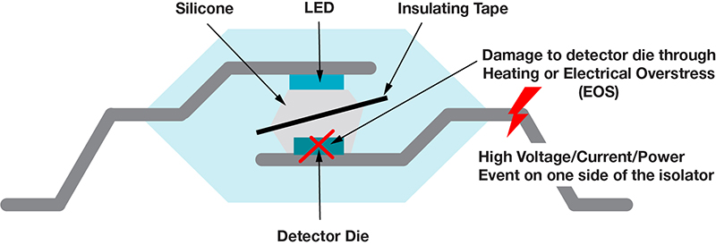
Figure 1: A cross section shows how an optocoupler is constructed and the possible effect of fault conditions.


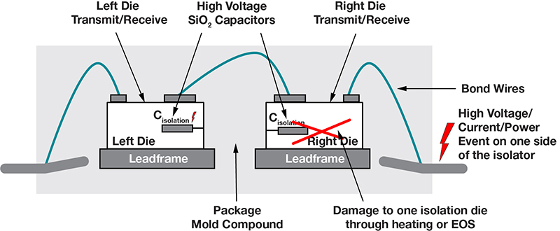
Figure 2: The digital isolator cross section shows how fault conditions can affect its insulating properties.

A high-voltage/high-current/high-power fault event on one side of the isolator can damage the circuits on that side. For example, events like short circuits, electrostatic discharge (ESD), and power transistor breakdown can force unintended high voltage and current into the isolator’s pins, damaging LEDs, photodetectors, transmit and receive circuits, and on-chip ESD protection. If there is enough power dissipated in the chip, there could also be significant structural damage to the circuits, such as fused silicone insulation, shorted high-voltage capacitor plates, or melted bond wires. Such structural damage can reduce the isolator’s insulation capability. The TI white paper, “Understanding failure modes in isolators,” discusses the effects of these fault events in more detail.

From the end-system perspective, isolation requirements may need to remain in force even after electrical and thermal stress events have impeded the isolator’s signal-transference operation. This is because damage to the isolation barrier can lead to secondary system failures, or the risk of an electrical hazard. For example, in Figure 3, a digital isolator protects the earthed control and communications module while the rest of the system floats. The effects of any faults in and around the digital isolator that may reduce the isolator’s insulation capability must be considered to avoid the effects of shorting DC- to earth.

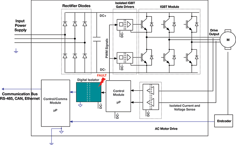
Figure 3: Failure of the digital isolator providing protective isolation in an AC motor drive could compromise the entire system if the fault resulted in a short to earth.

The practice of safety limiting is designed to minimize potential damage to the isolation barrier should the isolator’s input or output circuitry fail. Isolator component standards define the safety-limiting values as the maximum input or output current (IS), the maximum input or output power (PS), and the maximum junction temperature (TS) the device can withstand in the event of a fault without compromising its isolation, even if the function of the coupling elements may be destroyed. Device manufacturers must specify these parameters, but it remains up to you to ensure that these values are not exceeded in the event of a fault or a failure so that there is no insulation breakdown.

As an example of manufacturer-supplied safety limits, Figure 4 shows the IS for different supply voltages and PS as a function of ambient temperature for TI’s ISO7741 digital isolator. These values are specified so that the device’s maximum safety junction temperature (TS = 150°C) is not exceeded. Based on these curves, for instance, at an ambient temperature of 100°C up to 600 mW of power may dissipate inside the device without any potential damage to the insulation.

Figure 4: The safety-limiting values for TI’s ISO7741 digital isolator show how much power dissipation a fault can impose without compromising the device’s isolation characteristics.

Circuits utilize safety-limiting parameters

The materials and circuit design parameters the manufacturer has adopted govern a device’s safety-limiting values. What the safety standards require is that optocoupler/digital isolator users provide adequate safety arrangements in their circuit design and ensure that the device’s application conditions not exceed the device’s safety-limiting values. Such safety arrangements might include current and voltage limiting that kicks in under fault conditions, or thermal management that prevents an operating temperature above a maximum value.

Let’s look at two example circuits for implementing safety limiting for a digital isolator. While these examples will not be exhaustive, identifying all possible faults and outcomes, they elucidate the principles of safety limiting and should provide a sense of how to approach safety limiting in your isolated-system designs.

For the first example, Figure 5 shows a digital isolator serving as the interface between an analog-to-digital converter (ADC) or analog front end (AFE) and a microcontroller (MCU). I’ll analyze this system for any one primary fault, including any secondary faults this single fault produces. (Additional circuits may be necessary to protect against multiple primary faults.) This analysis will focus on the MCU side for safety limiting, although you can apply the same principles for the ADC/AFE side as well.

In this example, a 24-V industrial power supply (variable up to 36 V) powers the MCU side (VIN24V). A DC/DC converter bucks this down to 5 V (VDC5V), followed by a low-dropout regulator (LDO) that creates a 3.3-V supply (VDC3P3V) for the MCU and the digital isolator. Current-limiting resistor RSUP is included in the supply path, and resistors ROUT and RIN are included in the input/output (I/O) path.

Figure 5: The digital isolator serves as an interface in this example, providing isolation between an ADC or AFE and an MCU.

Let’s examine some faults and their implications on safety limiting.

  • Primary fault #1: Internal short in the isolator from VCC1 to GND1. The short circuit offers a resistance, RFAULT, from VCC1 to GND1. Using the maximum power transfer theorem, the maximum power dissipation within the isolator occurs when RFAULT = RSUP. The maximum power dissipation is equal to (VDC3P3V)2/(4 × RSUP). For very low values of RFAULT, the current through RSUP and VCC1 equals 3.6 V/RSUP. RSUP must be designed to dissipate this power. The power dissipated in the isolator itself, however, is very low (because RFAULT ~ 0 Ω). Example: If RSUP = RFAULT = 20 Ω, the maximum power dissipation in the isolator is (3.6 V)2/(4 × 20 Ω) = 0.162 W. According to its spec sheet, this is well within the ISO7741’s safety-limiting power. For cases where RFAULT ~ 0 Ω, the 20 Ω RSUP must be a 0.65-W resistor to account for the power it will need to dissipate. A higher value of RSUP is always beneficial, since it reduces power dissipation under fault conditions. However, you must also consider the voltage drop across RSUP in normal operation. An isolator with a wide supply range (such as the ISO7741, which supports operation down to 2.25 V) or a very low-power isolator like the ISO7041 (which consumes only 100 µA/channel at 1 Mbps) are options that can support a higher value of RSUP.
  • Primary fault #2: Input-to-output short circuit in the 24-V to 5-V DC/DC converter. In this case, the 24-V system supply (variable to 36 V) appears on the LDO input. To prevent further propagation of the fault, you must design the LDO to handle 36 V at its input. The isolator would likely not be able to withstand this voltage.
  • Primary fault #3: Input-to-output short circuit in the LDO. In this case, the 5-V input of the LDO occurs at its output. To prevent further propagation of the fault, the digital isolator must be able to handle 5 V on its supply (the ISO7741 meets this requirement). You must also consider any damage to the MCU (if the MCU cannot support 5 V on its supply). In the worst case, the MCU I/O pins are damaged and offer low impedance to supply or ground.
  • Primary fault #4: Short to ground or supply on the MCU IN and OUT pins. In this case, the current into the isolator pins can be higher than in normal operation. Resistors ROUT and RIN can help keep this current within safety limits. For example, ROUT = RIN = 100 Ω limits the current through the isolator’s I/O pins to 50 mA for 5-V conditions, which is well below the ISO7741’s safety-limiting current.

For the second example, an isolated digital input using the ISO1211 as shown in Figure 6.


Figure 6: In this example the isolated digital input circuit uses the TI ISO1211.

The isolated digital inputs receive signals from field sensors and interface them to a host programmable logic controller. The voltage input is nominally 24 V, but with variation can be as high as 36 V. The ISO1211 uses an external RSENSE resistor to provide a precise limit to the current drawn into the SENSE terminal. The external resistor RTHR can adjust the digital input’s voltage threshold. For an 11-V input threshold and a 2-mA current limit, the values of RSENSE and RTHR are 562 Ω and 1 kΩ, respectively (see the ISO1211 data sheet for details).

  • Primary fault #1: Internal short circuits inside the ISO1211 result in a low impedance of RFAULT between the SENSE and FGND pins. As before, the worst-case power dissipated inside the ISO1211 is (36V)2/(4 × RTHR). With RTHR = 1 kΩ, the worst-case power is 0.324 W, which is within the safety-limiting power for the ISO1211.
  • Primary fault #2: A short circuit on external resistor RTHR. The built-in current limit on the ISO1211 limits the current draw from the pin to a value set by RSENSE. Resistor RTHR has no significant role to play in determining the input current, so shorting RTHR does not change the current going into the ISO1211 or the power dissipation very much.
  • Primary fault #3: The input voltage rises to 60 V. Safety digital input systems must consider the 24-V industrial supply rising to 60 V under fault conditions. The ISO1211 can tolerate 60 V on its input pins while maintaining the current limit of 3.1 mA (RSENSE = 562 Ω). The maximum power dissipated is 60 V × 3.1 mA = 186 mW, well within the safety-limiting power of the ISO1211.

These two examples demonstrate how to analyze and mitigate different faults in the context of safety-limiting values. Based on the actual application and safety goals, though, you may need to take additional measures.

Conclusion

When using isolators it is important to understand their safety-limiting values, and to make provisions in your design to meet these values. Failure to design for safety limits could result in faults generating extensive system damage and possible fire and electrical hazards should the isolator’s barriers fail. The example circuits demonstrate ways to ensure the maintenance of safety-limiting values under fault conditions.


Satellite state of health: how space-grade ICs are improving telemetry circuit design

$
0
0
Because satellites on space missions are inaccessible once launched, acquiring accurate telemetry data to monitor the state of health of the satellite sub-systems can help set a baseline to indicate a working system, while fluctuations can indicate failures...(read more)

How accurate sensing in HVAC systems improves efficiency and saves consumers money

$
0
0

When designing for increased efficiency in heating, ventilation and air-conditioning (HVAC) systems, sensor accuracy and consistency have a significant effect. A system’s ability to accurately sense and measure temperature and humidity levels of inside and outside air sensors, damper controls, thermostats and fans minimizes system run time because the system can use more data to make better decisions. Along with proper HVAC implementation and maintenance, choosing the right sensor can save consumers as much as 25%.

When designing HVAC systems like the one shown in Figure 1, sensor accuracy, repeatability and overall reliability are extremely important.


Figure 1: A commercial or residential HVAC system

HVAC operation and efficiency

An HVAC system includes sensors throughout the structure, located in the mixed and supply air ducts and the outside and return air ducts, as well as in the thermostat. These sensors provide the raw data from which the controller manages the system’s performance. In primitive HVAC systems, there might only be temperature sensors located in some of the positions shown in Figure 1, and they might contain the oldest technology available (negative temperature coefficient thermistors [NTCs] and resistive temperature detectors). Modern systems might include two enthalpy economizer sensors, with one located in the return air path and one in the outdoor air path. When the thermostat is adjusted or the mixed-air temperature goes above a setpoint, the air with the lower enthalpy (from the outdoor or return air) is brought into the conditioning section of the air handler. This is a method of controlling outdoor air usage. It may appear wasteful to cool outdoor air at higher temperatures than return air, but the amount of mechanical cooling required to dehumidify air often exceeds that required to lower the dry-bulb temperature.

In buildings with substantial moisture generation, potentially from a kitchen or shower, this type of control sequence can result in substantial savings compared to methods that include using a dry-bulb temperature sensor high limit alone. Using enthalpy modules is significant, as about 50% of the cooling capacity of an air-conditioning system is used to dehumidify conditioned air, removing latent heat before the sensible heat temperature begins to drop.

HVAC systems without humidity sensors will not provide the cooling necessary to dehumidify the air before it enters the building. Using a single enthalpy economizer instead of dry-bulb temperature lowers cooling costs in most climates. And while these systems are effective and provide improvement over temperature-only systems, a second combined sensor module in the system adds another measurement location for data, and thus an opportunity to increase system efficiency.


Improve system operating costs and efficiency

 Explore the HDC2022 integrated sensor and TMP61 linear thermistor.

Why accuracy and consistency matter

Since an HVAC system comprises thermostats and wet bulbs that contain temperature and humidity sensors reporting to a central control system, inaccurate sensors can prematurely or falsely trigger the control system if the accuracy is off. A system error as small as ±1°C or 5% relative humidity equates to noticeable additional costs or potential savings, while also affecting electromechanical equipment lifetimes.

For example, a humidity sensor with a typical relative humidity accuracy of 5% is capturing a time zero reading. Over time, given stresses on a system, such as high temperature or contamination, the sensor will drift. Understanding drift is paramount to understanding system efficiency over time, and minimizing drift can enable better performance.

Technological advancements have made it possible to integrate sensing elements with low drift and high accuracy. The HDC2022 is a factory-calibrated integrated humidity and temperature sensor with a typical relative humidity of 2%; a 0.25% relative humidity long-term drift; and a hydrophobic IP67 filter that protects against water and dust and is less susceptible to condensation than a device without a filter. These humidity sensors have an integrated temperature sensor with better than 1°C accuracy.

Even with such high-performance sensors, you need to consider impacts to accuracy beyond the sensor. Placing printed circuit boards in an enclosure for protection will require compensation to account for differences between that enclosed environment and what the user may experience.

These same concepts apply to independent temperature measurements. A compressor discharge temperature could be 110°C and rise as high as 135°C or 140°C when malfunctioning. A typical temperature sensor with an accuracy of ±3°C to ±5°C and a long-term drift of ±5°C to ±10°C would leave 15°C of design margin for the compressor. As the compressor ages, this sensor drift limits compressor efficiency by forcing it to shut down prematurely.

A linear thermistor such as the TMP61 offers inherently low long-term drift and is capable of 150°C, at a cost similar to NTC thermistors. Its linearity enables improved accuracy with software techniques such as analog-to-digital oversampling to increase resolution and reduce the effect of noise. Its high accuracy and low long-term drift enable the compressor to reduce protection margins, allowing the system to shut down less often to prevent overheating, which leads to greater efficiency.

Conclusion

When designing HVAC systems, you should consider component and circuit cost, accuracy, repeatability, low drift over time, and general reliability in order to meet design requirements. Choosing the right sensors for your HVAC implementation not only makes designs better – it can also lower energy consumption and maintenance costs dramatically when compared to older systems.

Additional Resources:

Compact. Precise. Connected. Increase productivity with intelligent edge computing across factory, building and grid automation

$
0
0

The world population is 7.8 billion and is on the rise, with an estimate of 10 billion by 2050. The growing population needs basic necessities such as food, clothing and ever-increasing comforts safely and securely. Industry 4.0 technologies today and upcoming Industry 5.0 innovations in smart manufacturing, smart buildings and smart grid can serve these needs.

High-performance multicore processing engines used in Industry 4.0 cloud architectures collect data from thousands of edge sensors and perform sophisticated analytics to manage plant operations. As end-to-end automation increases, the number of sensors and corresponding data that requires managing is also increasing exponentially. A smart factory could have more than 50,000 sensors and generate several petabytes daily; even a standard office building can generate hundreds of gigabytes of data.

The International Data Corp. estimates that by 2022, 40% of data will be stored, managed, analyzed and kept right where it was produced, also known as “at the edge.” The evolution of computing outside the cloud has created a need for compact, precise and connected edge devices. These edge devices have three key requirements: real-time computing, multiprotocol industrial networking capabilities, and web service capabilities deployable in the field. Figure 1 illustrates these requirements in industrial applications.

TI’s AM64x family of Sitara™ real-time networked processors directly addresses these needs.

Figure 1: Intelligent edge-computing requirements

Systems that can benefit from the features in the AM64x family include AC servo motor drives, industrial programmable logic controllers (PLCs), motion controllers in factory automation, Internet of Things, gateways in building automation, data concentrators in grid automation, high-precision data-acquisition systems, 3D cameras and many more.

AC servo motor drive example

Consider a servo drive like the one in Figure 2 – a basic element of modern automation. Servo drives control the motors in everything from CNC machines, robotics, conveyor belts, warehouse automation and many more. The AM6442 for example, has four high-performance Arm® Cortex®-R5F cores running at up to 800 MHz each, offering a total of 6,400 real-time Dhrystone million instructions per second (DMIPS) and enabling high-precision motor-control loops with cycle times as low as 3 µs and extremely low jitter.

Integrated industrial communications make it possible for this same motor drive to communicate in real time with industrial PLCs or motion controllers using standards such as EtherCAT, Profinet and Ethernet/IP – without requiring additional field-programmable gate arrays (FPGAs) or application-specific integrated circuits (ASICs). You can use the on-chip Cortex-A53 processing cores to run a high-level operating system (OS) like Linux® and offer intelligent services such as remote diagnostics, failure monitoring, vibration monitoring and system configurability to implement on-demand business policies.

A processor that integrates multiple functions is more than 50% smaller than a multichip solution, enabling more compact drive systems. Designed in a 16-nm process, the power consumption of the AM64x – less than 1W to 2 Watts depending on the configuration – simplifies thermal design results in its compact size.


Figure 2: Compact, Precise, Connected servo drives


Real-time computing ability

The AM64x family uses Arm Cortex-R5F processing cores (as opposed to other Arm processing cores such as Cortex-M7) to enable multicore capability for embedded systems that require reliability, high availability and low-latency real-time responses. The AM6442 and AM6441’s four Cortex-R5F cores have a total performance of 5,300 real-time DMIPS. The Cortex-R5F includes low-latency interrupt technology that enables the interruption and restarting of long multicycle instructions.

Real-time multiprotocol industrial networking capabilities

Ethernet is becoming the de facto industrial communications standard, replacing serial field buses in factories, buildings and grid infrastructures. But standard Ethernet is also nondeterministic, and modern factory automation requires deterministic operation and time synchronization. The standards developed to address this inherent incompatibility require special FPGAs or ASICs, increasing system cost and size.

Integrated industrial connectivity is central to the AM64x architecture. Each device features multiple Ethernet ports to support industrial switch implementations such as time-sensitive networking (TSN) up to gigabit speeds, as well as EtherCAT®, PROFINET®, ETHERNET/IP® and others.

The AM64x family also integrates complete software stacks for these protocols, making it easy to design edge devices that seamlessly connect to the factory infrastructure. AM64x protocol support also includes IO-Link Master and acting as a gateway from IO-Link to any of the industrial Ethernet protocols and motor encode position EnDat 2.2 and HIPERFACE DSL®.

Web service capabilities deployable in the field

Remotely managing devices – drives, sensors and gateways – in Industry 4.0 could be based on predictive maintenance algorithms running in the system, sending alerts to the cloud or infrastructure. The on-chip Cortex-A53 core(s) in the AM64x perform this task without disrupting service.

You can also run a high-level OS such as Linux and a web or application server to implement different business models. Two cores running at 1 GHz each offer enough performance to handle the increasing amount of multiple services without disrupting real-time computing and networking traffic. Linux also enables faster applicationdevelopment, with features continuously added in kernel revisions. The AM64x’s mainline Linux support simplifies code-base conversions from one kernel to the next.

The AM64x family has multiple pin-to-pin compatible devices shown in Table 2. You can start with a lower-featured device and migrate to a higher-performing device as your design needs evolve, while keeping the same printed circuit board design.

Function

Detailed features

AM6442

AM6441

AM6421

AM6412

AM6411

Real-time computing

MCU cores

4 Cortex-R5Fs

4 Cortex-R5Fs

2 Cortex-R5Fs

1 Cortex-R5F

1
Cortex-
R5F

Frequency (MHz, each core)

800

800

800

800, 400

800, 400

DMIPS (total): Cortex-R5F at 2 DMIPS/Hz

6,400

6,400

3,200

1,600

1,600

High-level OS and services

MPU cores

2 Cortex-A53s

1 Cortex-A53

1 Cortex-A53

2 Cortex-A53s

1 Cortex-A53

Frequency (MHz, each core)

1,000

1,000

1,000

800, 1,000

800, 1,000

DMIPS (total): Cortex-A53 at 3 DMIPS/Hz

6,000

3,000

3,000

6,000

3,000

System control

Dedicated microcontroller (MCU) core with functional isolation

1 Cortex-M4 at 400 MHz

1 Cortex-M4 at 400 MHz

1 Cortex-M4 at 400 MHz

1 Cortex-M4 at 400 MHz

1 Cortex-M4 at 400 MHz

Connectivity

Real-time industrial Ethernet

Yes

Yes

Yes

No

No

TSN

Yes

Yes

Yes

Yes

Yes

Security

IP authentication and protection (confidentiality), anti-cloning protection, cryptography accelerators, trusted execution environment

Yes

Yes

Yes

Yes

Yes

Safety

Independent Cortex-M4 MCU channel from the main domain, error monitoring

Yes

Yes

Yes

Yes

Yes

Table 2: The pin-to-pin compatible AM64x family

Conclusion
TI’s new family of AM64x devices combine real-time computing performance, integrated networking options and the ability to implement configurable web services in a small power envelope. With five pin-to-pin compatible devices, the AM64x family enables you to design next-generation compact, precise and connected edge devices for modern automation.
 
Additional resources

The value of a thin, isolated power solution

$
0
0

Faced with shrinking space constraints and increased robustness requirements, industrial and automotive power-supply designers must carefully choose the best power design topologies to meet their application needs. Isolated choices include modules as well as discrete and integrated solutions; each has its own trade-offs. Modules are encapsulated solutions with common input/output requirements, but they have limited temperature and isolation ratings. Discrete solutions are customized designs using individual components, but they require a large engineering effort. Integrated solutions use transformers inside the package for a lower profile solution, but they have lower power outputs.

Modules and discrete solutions use transformers or inductors to convert electric energy. The transformer is a tall component, which causes modules and discrete solutions to have significant height. Figure 1 shows a 3D view of a module and a top-down view of a discrete solution.

Figure 1: Isolated power solutions: module on the left, discrete on the right

Applications requiring low board thickness are limited by the height of the solution. For example, telecommunication racks use slotted cards to add or replace servers. The thinner these cards are, the more server slots can fit in each rack. Industries like telecommunications and consumer electronics pushing for low-profile designs can benefit from a thin, integrated power solution.

Thin solutions have a mechanical advantage as well. Compared to other printed circuit board (PCB) components, transformers are tall – like a high-rise in the middle of a residential community. These tall components act like cantilevers and are susceptible to strong physical perturbations on the PCB, just like a high-rise in an earthquake. Cantilever vibration modes lead to lateral stresses at the top of the component, as illustrated in Figure 2.

Figure 2: Discrete solution with transformer flexibility illustrated in white

Lateral stress can cause transformer pads to lift or components to desolder from the PCB. This can be a huge reliability issue in rugged application environments that will experience impacts and vibrations. For example, isolated drivers powering AC motors can experience vibrations related to motor speeds during operation. If the vibrations get too violent, a motor can cause its own failure by disconnecting the transformer from its power-stage gate driver.

Even with minimal vibrations, one unexpected impact can potentially disable motor drives. Imagine in factory automation that an impact causes a motor failure, slowing down or stopping production. Or for an electric vehicle, hitting a speed bump too fast could potentially disable the electric motor. Thin, low-profile designs are critical for circuit lifetime reliability in environments with vibrations and impacts, such as automotive electric motors and industrial automation.

TI's UCC12051-Q1 is an integrated isolated DC/DC converter that leverages transformer-in-package technology, providing 500 mW of isolated power in a low-profile 16 pin small-outline integrated circuit (SOIC16-DW) package. The device is operable in extended ambient temperatures from -40°C to 125°C and features 5-kV reinforced isolation.

Thin board designs allow for smaller, denser systems, and are more mechanically robust to vibrations and perturbations. The UCC12051-Q1 enables low-profile power for thinner board designs compared to modules and integrated solutions. Medical and consumer industries can benefit from lower profiles systems, and telecommunication and industrial industries can benefit from increased reliability and power density.

From car access to tire pressure monitoring, discover how Bluetooth® Low Energy is changing the connected car

$
0
0


Bluetooth® Low Energy is on a path to become ubiquitous. The Bluetooth Special Interest Group estimates that by 2024, all new phones, tablets and laptops will support Bluetooth Classic and Bluetooth Low Energy. They also expect 35% of devices to ship with single-mode Bluetooth Low Energy by 2024, which represents 300% growth in annual shipments. 

The reason for this is the versatility of Bluetooth Low Energy. Bluetooth Low Energy continues to expand its capabilities to meet new applications. Features including LE audio, mesh, positioning services and many more have been added to adapt to the growing demand in applications such as asset tracking, health and fitness, Internet of Things, access control and more. Due to its versatile capabilities and widespread use in smartphones which enables interoperability and immediate deployment in existing systems, Bluetooth Low Energy is becoming the go-to standard for a variety of automotive applications. 

Recent trends suggest that automotive manufacturers are embracing Bluetooth Low Energy for tire pressure monitoring systems (TPMSs), cable replacement, telematics, wireless battery management systems, personalization, smart wearables and LE Audio. Let’s explore a few of these applications. 

Stand-alone Bluetooth Low Energy benefits in automotive

Cars today tend to have many different wireless technologies on board, including low-frequency radio, ultra-high-frequency radio, Wi-Fi® and Bluetooth Classic. All of these technologies require some amount of power in order to operate, but what happens when the car is off? In most cases, various systems are also powered off, but preserving some form of wireless connectivity might still be necessary. For example, when returning to a parking lot, we would still like to perform actions such as turning on the headlights, air conditioning and unlocking the car. 

Usually, the car is equipped with a Wi-Fi and Bluetooth combination chip. So what’s the problem? Power. It is possible to power down these chips partially, but they require their host module to be in sleep mode (as opposed to being powered off completely), which ultimately wastes power. The solution is a single, power-efficient wakeup source for the vehicle’s wireless systems.

Stand-alone Bluetooth Low Energy is a single chip capable of performing Bluetooth Low Energy only. 

From a connectivity standpoint, it’s possible to achieve a better power budget by adding a stand-alone Bluetooth Low Energy node in the head unit or telematics box that acts as a wakeup source for the entire system. Once a smartphone or key fob comes into range, the node sends a wakeup signal that turns on the other wireless systems on the vehicle. 

Beyond power savings, using a stand-alone Bluetooth Low Energy chip has these advantages:

  • You can leverage stand-alone Bluetooth Low Energy chips to act as a central node for TPMS nodes or as a passive node for car access applications.
  • TI offers Bluetooth Low Energy and microcontroller (MCU) combination chips where the stand-alone Bluetooth Low Energy chip acts not just as a wireless transceiver but as a stand-alone MCU to perform housekeeping tasks or monitor other peripherals.
  • You can leverage stand-alone Bluetooth Low Energy nodes as range extenders by using a single node as Central and Peripheral simultaneously.

Bluetooth Low Energy benefits in TPMSs

Bluetooth Low Energy’s versatility and compatibility with smartphones enable a variety of applications, which have inspired designers to attempt consolidating wireless technologies in the vehicle into Bluetooth Low Energy. A great example is TPMSs.

In the past, drivers would have to check the pressure at each tire separately. As technology progressed and wireless communication has become simpler to design and maintain, TPMS has become a passive safety standard in the automotive world.

Most TPMSs use two separate integrated circuits (IC) – a low-frequency radio IC and an ultra-high-frequency IC. The downside is that this method requires the vehicle’s central processing unit (CPU) to use a separate, dedicated receiver for both wireless technologies, requiring maintenance of each.

Alternatively, we could design the TPMS nodes with Bluetooth Low Energy only, which offers long range support and power efficiency that allows for higher robustness and longevity as well as native support in smartphones which allows for excellent interoperability between the vehicles other Bluetooth Low Energy systems. Moreover, TPMS can be incorporated as part of a Bluetooth Low Energy network in the vehicle.

By using smart and efficient design, designers can save costs by combining multiple applications on a single Bluetooth Low Energy node. For example, since the vehicle’s main CPU already includes Bluetooth Low Energy, you can leverage this node to act as a data collector for the TPMS, increasing efficiency and reducing the total amount of wireless nodes in the vehicle, which in turn saves total system costs and increases node interoperability.

Conclusion

Bluetooth Low Energy brings many benefits to the world of automotive by offering multiple possibilities through a single wireless technology, including power savings, interoperability, and hardware and software reuse, while also eliminating the need to certify, maintain and develop multiple wireless technologies.

Leveraging the SimpleLink™ CC13x2 and CC26x2 software development kit makes it possible to use Bluetooth Low Energy as a unified hardware and software baseline, which also makes it easier to develop, port and debug the system, increase robustness and traceability, and help save total system costs.

Additional resources


Designing with low-power op amps, part 1: Power-saving techniques for op-amp circuits

$
0
0

In recent years, the popularity of battery-powered electronics has made power consumption an increasing priority for analog circuit designers. With this in mind, this article is the first in a series that will cover the ins and outs of designing systems with low-power operational amplifiers (op amps).

In the first installment, I will discuss power-saving techniques for op-amp circuits, including picking an amplifier with a low quiescent current (IQ) and increasing the load resistance of the feedback network.

Understanding power consumption in op-amp circuits

Let’s begin by considering an example circuit where power may be a concern: a battery-powered sensor generating an analog, sinusoidal signal of 50 mV amplitude and 50 mV of offset at 1 kHz. The signal needs to be scaled up to a range of 0 V to 3 V for signal conditioning (Figure 1), while saving as much battery power as possible, and that will require a noninverting amplifier configuration with a gain of 30 V/V, as shown in Figure 2. How can you optimize the power consumption of this circuit?

Side-by-side graphs of input and output voltage of battery-powered sensor

Figure 1: Input and output signals

 Circuit diagram of noninverting amplifier configuration

Figure 2: A sensor amplification circuit

Power consumption in an op-amp circuit consists of various factors: quiescent power, op amp output power, and load power. The quiescent power, PQuiescent, is the power needed to keep the amplifier turned on and consists of the op amp’s IQ, which is listed in the product data sheet. The output power, POutput, is the power dissipated in the op amp’s output stage to drive the load. Finally, load power, PLoad, is the power dissipated by the load itself. My colleague, Thomas Kuehl, in his technical article, “Top questions on op-amp power dissipation – part 1,” and a TI Precision Labs video, “Op Amps: Power and Temperature,” define various equations for calculating power consumption for an op amp circuit.

In this example, we have a single-supply op amp with a sinusoidal output signal that has a DC voltage offset. So we will use the following equations to find the total, average power, Ptotal,avg. The supply voltage is represented by V+. Voff is the DC offset of the output signal and Vamp is the output signal’s amplitude. Finally, RLoad is the total load resistance of the op amp. Notice that the average total power is directly related to IQ while inversely related to RLoad.

Equations used to find the total, average power, of a single-supply op amp with a sinusoidal output signal that has a DC voltage offset.

Picking a device with the right IQ

Equations 5 and 6 have several terms and it’s best to consider them one at a time. Selecting an amplifier with a low IQ is the most straightforward strategy to lower the overall power consumption. There are, of course, some trade-offs in this process. For example, devices with a lower IQ typically have lower bandwidth, greater noise and may be more difficult to stabilize. Subsequent installments of this series will address these topics in greater detail.

Because the IQ of op amps can vary by orders of magnitude, it’s worth taking the time to pick the right amplifier. TI offers circuit designers a broad selection range, as you can see in Table 1. For example, the TLV9042, OPA2333, OPA391 and other micropower devices deliver a good balance of power savings and other performance parameters. For applications that require the maximum power efficiency, the TLV8802 and other nanopower devices will be a good fit. You can search for devices with your specific parameters, such as those with ≤10 µA of IQ, using our parametric search.

Typical specifications

TLV9042

OPA2333

OPA391

TLV8802

Supply voltage (VS)

1.2 V-5.5 V

1.8 V-5.5 V

1.7 V-5.5 V

1.7 V-5.5 V

Bandwidth (GBW)

350 kHz

350 kHz

1 MHz

6 kHz

Typical IQ per channel at 25°C

10 µA

17 µA

22 µA

320 nA

Maximum IQ per channel at 25°C

13 µA

25 µA

28 µA

650 nA

Typical offset voltage (Vos) at 25°C

600 µV

2 µV

10 µV

550 µV

Input voltage noise density at 1 kHz (en)

66 nV/√Hz

55 nV/√Hz

55 nV/√Hz

450 nV/√Hz

Table 1: Notable low-power devices

Reducing the resistance of the load network

Now consider the rest of the terms in Equations 5 and 6. The Vamp terms cancel out with no effect on Ptotal,avg and Voff is generally predetermined by the application. In other words, you often cannot use Voff to lower power consumption. Similarly, the V+ rail voltage is typically set by the supply voltages available in the circuit. It may appear that the term RLoad is also predetermined by the application. However, this term includes any component that loads the output and not just the load resistor, RL. In the case of the circuit shown in figure 1, RLoad would include RL and the feedback components, R1 and R2. Hence, RLoad would be defined by Equations 7 and 8.

Equations to define Rload

By increasing the values of the feedback resistors, you can decrease the output power of the amplifier. This technique is especially effective when Poutput dominates PQuiescent, but has its limits. If the feedback resistors become significantly larger than RL, then RL will dominate RLoad such that the power consumption will cease to shrink. Large feedback resistors can also interact with the input capacitance of the amplifier to destabilize the circuit and generate significant noise.

To minimize the noise contribution of these components, it’s a good idea to compare the thermal noise of the equivalent resistance seen at each of the op-amp’s inputs (see Figure 3) to the amplifier’s voltage noise spectral density. A rule of thumb is to ensure that the amplifier’s input voltage noise density specification is at least three times greater than the voltage noise of the equivalent resistance as viewed from each of the amplifier’s inputs.

 Graph of resistor thermal noise at various temperatures

Figure 3: Resistor thermal noise

Real-world example

Using these low-power design techniques, let’s return to the original problem: a battery-powered sensor generating an analog signal of 0 to 100 mV at 1 kHz needs a signal amplification of 30 V/V. Figure 4 compares two designs. The design on the left uses a typical 3.3-V supply, resistors not sized with power-savings in mind and the TLV9002 general-purpose op amp. The design on the right uses larger resistor values and the lower-power TLV9042 op amp. Notice that the noise spectral density of the equivalent resistance, approximately 9.667 kΩ, at the TLV9042’s inverting input is more than three times smaller than the broadband noise of the amplifier in order to ensure that the noise of the op amp dominates any noise generated by the resistors.

Schematic circuits showing comparison between typical op-amp design and a low-power op amp design

Figure 4: A typical design vs. a power-conscious design

Using the values from Figure 4, the design specifications and the applicable amplifier specifications, Equation 6 can be solved to give Ptotal,avg for the TLV9002 design and the TLV9042 design. For your reading convenience, Equation 6 has been copied here as Equation 9. Equations 10 and 11 show the numeric values of Ptotal,avg for the TLV9002 design and the TLV9042 design, respectively. Equations 12 and 13 show the results.

Equations showing the numeric values of Ptotal,avg for TLV9002 design and TLV9042

As can be seen from the last two equations, the TLV9002 design consumes more than four times the power of the TLV9042 design. This is a consequence of a higher amplifier IQ, demonstrated in the left terms of Equations 10 and 11, along with smaller feedback resistors, as accounted for in the right terms of Equations 10 and 11. In the case where more IQ and smaller feedback resistors are not needed, implementing the techniques described here can provide significant power savings.

Conclusion

I’ve covered the basics of designing amplifier circuits for low power consumption, including picking a device with low IQ and increasing the values of the discrete resistors. In the next installment of this series, I’ll take a look at when you can use low-power amplifiers with low voltage supply capabilities.

Additional resources

Enabling functionally safe and secure electric automotive powertrains using C2000™ real-time MCUs

$
0
0

Jürgen Belz, senior consultant, functional safety and cybersecurity at Prometo, co-authored this technical article.

The migration from internal combustion engines (ICEs) to electric vehicles (EVs) requires at least five new electrical/electronic/programmable electronic (E/E/PE) systems. Figure 1 depicts these systems within an EV. 

Figure 1: Block diagram of a typical EV powertrain 

In order to zero out tailpipe emissions and reduce continued reliance on fossil fuels, refuelling EVs happens at a charging station. These EV charging stations could be supplied with renewable energy sources like solar and wind, which increases the positive impact of EVs on the environment. The onboard charger forms a functional unit with the high-voltage battery, which ensures fast, efficient charging while still protecting the battery from overcharging. These and other safety requirements are described in International Organization for Standardization (ISO) 6469 parts 1, 2 and 3 – the standard that governs the high-voltage electrical safety requirements for electric road vehicles. 

All Electronic Control Units (ECUs) in an EV require a 12-V battery charged by a high-voltage-to-low voltage DC/DC converter, which helps establish galvanic separation between the low-voltage (12-V) battery and the high-voltage (400 V or 800 V) battery. The inverter and the electric machine (propulsion motor) deliver torque for controlled motion. Very compact and high-power-density permanently excited synchronous machines are usually deployed in an EV propulsion motor. At lower power levels, asynchronous machines have found limited use in EVs. Functional safety aspects of this high-voltage-to-low voltage DC/DC converter help guarantee the operation of all ECU features while the EV is in motion and the EV Traction Inverter (EVTI) are outlined in ISO 26262:2018. 

For instance, for a vehicle with an ICE, the operating time (or power-on hours) of a semiconductor component is between 8,000 and 10,000 hours. With an EV, this increases to 30,000 hours or more. The reason: semiconductor components have to remain powered up not only when the vehicle is being driven, but also when the vehicle is charging. This amount of power influences, for example, the calculation of the probabilistic metric for random hardware failures according to ISO 26262. For engineers, this amount of power means that they must develop a system that on average has a fivefold lower probability of dangerous component failures or failure in time.

 In an electrified powertrain, the C2000™ real-time microcontroller (MCU) typically addresses power conversion and communicates with a general-purpose MCU connected to the bus vehicle, managing the highest level of security, shown in Figure 2.


Figure 2: C2000 real-time control in an electric powertrain 

You might still want to consider encrypted communication between the communication MCU and the C2000 real-time controller, typically used for over-the-air upgrades. In such cases, you need to assess the threat level and define a security strategy at the system level to leverage the various security enablers that the C2000 real-time MCU offers, listed in Figure 3. 

Figure 3: C2000 supported enabler status

Some of the technical features supporting these security enablers include:

  • The ability to protect memory blocks.
  • Memory zone ownership by bus masters such as the C28x central processing unit (CPU), control law accelerator and direct memory access.
  • Execute-only protection for certain memory regions (with callable secure copy and secure cyclic redundancy check software Application Programming Interface functions available in the boot read-only memory).
  • Protecting the CPU from improper access through debugging ports and logic while it is executing code from secure memory regions (also called secure Joint Test Action Group).
  • Unique identification for each product.
  • Hardware acceleration engine for 128-bit Advanced Embedded Standard (AES) encryption.
  • Secure boot.

Conclusion

Because the electric drives or voltage converters have to be functionally safe, high-voltage safe, power-efficient and cost-effective, the challenges and complexities increase exponentially. Designing with C2000 real-time MCUs can help solve these challenges by giving EV charging designers the option to use a single device that enables all of these requirements.

Additional resources


How current-sense amplifiers monitor satellite health

$
0
0

Several commercial satellite companies have entered the space sector with a major impact, revolutionizing this once largely government-funded activity. The need to launch more satellites per year is driven by companies wanting to develop telecommunications mega-constellations, robust radar networks and enhanced optical imaging platforms into low-Earth orbit, medium-Earth orbit and geostationary equatorial orbit. These missions have led designers to pivot from basing satellite designs on simple discrete components such as op-amps or transistors in favor of using more highly integrated circuits, which helps save time with design effort, assembly, and test.

Current-sense amplifiers (CSAs) are a good fit in a wide variety of applications throughout a satellite’s electronic systems. In this article, I’ll discuss how CSAs can monitor the health and functionality for satellite power distribution systems and electrical motors by implementing features such as power-rail current monitoring, point-of-load detection and motor-drive control.

Satellite current monitoring

One of the most common use cases for CSAs in a satellite is to monitor the main power-rail input current to detect single-event transients. Because a CSA can handle the application of voltages greater than the supply voltage to its input pins, it offers more design flexibility than traditional operational amplifiers or other discrete solutions, where the common-mode input pin voltage is bound by the supply voltages of the amplifier.

A CSA enables both high- and low-side sensing designs; you can configure your system to have a shunt resistor before or after the load, and can monitor for anomalies in the expected delivered load current such as an overcurrent event. Table 1 summarizes the trade-offs of high- and low-side implementations.


High side

Low side

Implementation

Differential input

Single or differential input

Ground disturbance

No

Yes

Common voltage

Close to supply

Close to ground

Common-mode rejection ratio requirements

Higher

Lower

Load short detection

Yes

No

Table 1: High-side vs. low-side sensing

Our QML Class V space-grade CSA, the INA901-SP, is capable of both high- and low-side sensing, with an input voltage ranging from –15 V to 65 V, a 50-krad(Si) radiation-hardened-assured (RHA) specification at a low dose rate and single-event latch up (SEL) immunity characterized up to an LETEFF = 75 MeV-cm2/mg SEL. The INA901-SP helps minimize the number of devices required to monitor supply-rail health and protect satellite systems from an overcurrent event.

Point-of-load detection

Leveraging a CSA for point-of-load detection is useful to collect data on vital system components to determine the health or power consumption of particular system loads. Using data from the CSA, the system can make data-driven decisions such as self-calibration or throttling load components to ensure proper operation outside normal operations. A CSA’s accuracy, high voltage range and supply voltage-independent common-mode range make it possible to more easily monitor mission-critical components and help ensure mission success.

Motor-drive applications

In motor-drive applications, the motor-driver circuitry generates pulse-width modulated (PWM) signals to precisely control a motor’s operation. These modulated signals are subject to the monitoring circuitry placed in line with each motor phase, which delivers feedback information for the control circuit. Because real-world amplifiers as opposed to theoretical amplifiers are less than perfect, the output can be affected by the failure of the amplifier to adequately reject the large PWM-driven input voltage steps of the common-mode voltage. Real-world amplifiers do not have infinite common-mode rejection, and undesirable fluctuations appear at the amplifier output corresponding to each input voltage step. Figure 1 shows the outputs of a competing device, while Figure 2 shows the INA240-SEP output.

Figure 1: Competitor output vs. PWM input

Figure 2: INA240-SEP output vs. PWM input

These output fluctuations can be fairly large, and depending on the characteristics of the amplifier, can take significant time to settle following the input transition. Leveraging the enhanced PWM rejection technology in the INA240-SEP helps provide high levels of suppression for large common-mode transients (ΔV/Δt) in systems that use PWM signals, which is especially useful in motor-drive and solenoid applications. This feature enables accurate current measurements with reduced transients and associated recovery ripple on the output voltage.

The INA240-SEP is an ultra-precise device packaged in space-enhanced plastic that is capable of –4-V to 80-V common-mode voltage with gain error of 0.2%; a gain drift of 2.5 ppm/°C; and an offset voltage of ±25 μV, which is part of TI’s radiation tolerant portfolio know as “Space Enhanced Plastic” (Space EP) to 30-krad(Si) RHA with SEL immunity up to 43 MeV-cm2/mg at 125°C, targeting low earth orbit applications.

Conclusion

Current sensing provides many benefits to a system, including optimized performance, improved reliability and condition monitoring to protect system vitals. Because space-grade CSAs enable direct measurements with highly accurate results, they help systems perform correctly for many years in the harshest environments.

Additional Resources

The top 5 design challenges of remote patient monitoring

$
0
0
(Note: A version of this article first appeared in Machine Design .) The wearable patient monitor market is growing fast. Remote patient-monitoring equipment provides a glimpse into the future of the Internet of Things in health care by enabling physicians...(read more)

Why precision matters with fully differential amplifiers

$
0
0

Differential signaling is becoming more popular in analog front ends, especially in factory automation designs, to interface with differential analog-to-digital converters (ADCs). In this article, I’ll discuss the advantages of a fully differential signal path, explain why precision is important and discuss how new fully differential amplifiers can meet precision challenges.

What is a fully differential amplifier?

A fully differential amplifier is a flexible device designed to provide a purely differential output signal centered at the user-configurable common-mode voltage. With this feature, the amplifier can control the output common-mode voltage independently from the differential voltage. The common-mode voltage is usually matched to the input common-mode voltage required by the ADC.


Increase the precision of your ADC driver.

 Learn more about the THP210 fully differential amplifier with ultra-low offset drift.


Advantages of fully differential amplifiers

Differential signaling is becoming more popular in analog front ends. Factory automation is a segment where differential ADCs are popular. As such, a low-noise fully differential amplifier provides the necessary noise immunity and increases the dynamic range.

A differential signal has several advantages over its single-ended counterpart, including:

  • Improved voltage swing. Both signals are out of phase, and the dynamic range is two times more than a single-ended output with the same voltage swing.
  • Noise immunity. Since a differential signal is the difference of two single-ended signals that are out of phase to each other, any common-mode disturbance, power-supply noise, ground disturbance or electromagnetic interference will affect both signals equally – and ideally cancel each other out.
  • Reduced harmonic distortion. Theoretical analysis of the distortion products of the differential output signal results in an even-order term cancellation. In reality, the distortion is also strongly dependent on the board layout and measurement setup.

Why is precision important?

Fully differential amplifiers typically drive high-resolution ADCs. The differential signal processing suppresses common mode, supply and ground disturbances. However, the offset, gain error and temperature drift of the preamplifier circuit can limit overall signal-chain accuracy.

You can cancel out the offset error voltage by applying a few calibration schemes. Figure 1 shows a simplified circuit that you can use for offset calibration in differential input applications. The inputs are shorted to ground and provide an accurate 0-V signal. The offset error can directly be read at the output of the amplifier at the downstream ADC and further post-processed via software on a microcontroller. You can learn more about this technique in the TI Precision Labs video, “Understanding and Calibrating the Offset and Gain for ADC Systems.”

Schematic showing a circuit that can be used for offset calibration in differential input applications

Figure 1: Offset calibration for differential signals

If the system allows, there are also ways to calibrate out the gain error. In order to minimize cost and complexity, many systems use one-point calibrations.

Gain and offset errors are common error sources that calibration techniques can cancel out by using calibration techniques. However, temperature drifts of the amplifier are sources that can dominate but are difficult or impossible to calibrate out. Temperature degradation is crucial for reliable measurements to improve the longevity of the equipment.

System designers often ask how to minimize these types of errors. The answer is simply to use devices with low drift specifications, such as the THP210 fully differential amplifier.

Let’s analyze the resulting drift error of a fully differential amplifier circuit. The main factors to consider when determining the error voltage over temperature are the:

  • Input offset voltage drift: VIO vs. temperature = 0.35 µV/°C.
  • Input bias current drift: IB vs. temperature = 15 pA/°C.
  • Input offset current drift: IOS vs. temperature = 10 pA/°C.

Figure 2 shows a fully differential amplifier configuration at a gain of 5 V/V with a feedback resistor network of 5 kΩ for R2/R4 and 1 kΩ for R1/R3, respectively. Both have tolerance of 0.1%.

Schematic showing a differential amplifier configuration

Figure 2: Error model of a fully differential amplifier

Equation 1 calculates the total voltage error over a temperature range from 25°C to 125°C:

This error voltage is naturally reflected on the output of the application.

Given the maximum values of the THP210, the total drift error ends up at 36 µV, an improvement that’s four times greater than precision fully differential amplifiers currently available.

Conclusion

Differential signaling applications provide clear advantages over single-ended signals in many systems. Advantages include an improved voltage swing, better noise immunity, better common-mode rejection properties and low harmonic distortion.

To achieve high accuracy for the differential amplifier circuit, my recommendations are to carefully consider both the selection of the external resistor network and the temperature degradation effects of the amplifier.

How to stack battery monitors for high-cell-count industrial applications

$
0
0

As we begin to see battery technology in more applications, new challenges arise. Many applications in the industrial space require higher cell counts than battery-powered applications such as cellphones and laptops. Industrial battery-management systems such as e-mobility, battery-backup units and vacuum cleaners can feature 12, 16, 24 or even more battery cells in series. Traditional battery monitors can only support 16 cells in series per device, which means that battery-management systems with more than 16 cells in series will require multiple battery monitor devices. Stacking multiple monitors will require extra components so that the monitors within the system can communicate with one another.

Stacking with TI’s BQ76952

The BQ76952 monitors the battery pack for several types of system faults. When one of these faults occur, the fault signal needs to be communicated to the protection field-effect transistors (FETs). All battery monitors in the stack need to connect to these FETs. The BQ76952 features high-side N-channel FET drivers, which are less practical to use in a stacked configuration. Instead, combining the protection signals at ground level will help control the low-side protection FETs.

Figure 1 shows a block diagram stacking two BQ76952 battery monitors. This configuration uses external circuitry to control low-side protection N-channel FETs. The I2C buses from each device are routed to a host microcontroller, with the upper device using a 2.5-kV I2C isolator. Compared to a design that features only one battery monitor, this example requires a few extra components in order to wake both monitors from shutdown mode. More components are also required for proper load detection functionality when the protection FETs are disabled.


Figure 1: Block diagram of a stacking configuration with BQ76952 battery monitors

Battery system protection with the BQ76952

Like the communication signals, you will also need to correctly configure the protection signals. The BQ76952 provides logic-level outputs that match the controls used for the high-side FET drivers. These outputs are driven based on the local low-dropout regulator (LDO) of each monitor, which has a programmable voltage up to 5 V. As I mentioned before, combining these signals from stacked devices helps control low-side N-channel FETs, as shown in Figure 2.


Figure 2: Combined protection solution for BQ76952 battery monitors

The BQ76952 includes a shutdown mode for lower current consumption. To wake up from shutdown mode and return to normal operation, you can use one of two methods:

  • Apply a voltage to the LD pin. A voltage on the LD pin normally occurs when a charger is connected.
  • Pull the TS2 pin (which provides a weak 5-V level with a 5-MΩ source impedance while in shutdown) to VSS.

Make sure that all monitors in the stack include a wakeup method so that the entire system will function correctly. Applying a voltage to the LD pin on the device by attaching a charger will also induce wakeup, but it is important to add appropriate circuitry to limit the voltage at each pin to the specifications in the datasheet.

The BQ76952 supports up to 400-kHz I2C, Serial Peripheral Interface (SPI) and High-speed Data Input/Output (HDQ) communications. Each device is configurable with a separate I2C address. Using the ISO1541 isolator facilitates communication to the upper device(s), as in our Industrial Battery Management Module for 20S Applications Reference Design. Another option is level-shifting using discrete circuitry. Figure 3 illustrates an example using discrete circuitry with SPI communications.


Figure 3: Serial communication in a stacked solution with BQ76952 battery monitors

Load detection with the BQ76952

The BQ76952 includes load-detection functionality to determine whether the load has been removed from a pack while the FETs are disabled. It is important to make sure that this signal is communicated across all devices in the stack, because otherwise the presence of a load determines the operating state of the battery monitors and all monitors in the stack should be in the same mode at any given time. You can use this detection functionality for recovery, after a short or overcurrent results in disabled FETs.

Load-detection functionality is designed for use with high-side FETs. With FETs off, the device will periodically source a 100-µA current out of the LD pin and measure the voltage of the pin. If the voltage is above a 4-V threshold, the device will detect whether the load has been removed. You can use this feature in a stacked configuration with low-side FETs and additional external circuitry. Figure 4 shows an example of a load-detection circuit.


Figure 4: Load detection in a stacked configuration with BQ76952 battery monitors

Cell balancing with the BQ76952

When using multiple battery monitors, the cells connected to the bottom device may become imbalanced with the cells connected to the top device. To avoid imbalances caused by unequal power dissipation within the stack, configuring each device in the stack to enable the same set of modules or components internally will keep their power dissipation balanced. Take care to balance any external circuitry powered from the LDOs of the stacked devices. If this is a concern, it is ok to draw the supply voltage for each monitor and their associated LDOs from the top of the stack.

A random cell-attach feature means that the device will still function as expected, regardless of how the battery cells are connected. This feature is not always supported in designs with multiple devices, however. Pay careful attention to the guidelines for each device and connect the cells properly, in a way that avoids blowing an inline fuse. The BQ76952 battery monitor supports production-line programming of settings into one-time programmable memory.

Conclusion

The emergence of battery power in industrial applications presents new engineering challenges. Because single battery monitors cannot support the high cell counts in these applications, stacking multiple devices is a necessity. TI’s latest portfolio of battery monitors can be stacked to meet this design requirement.

Additional resources

How to optimize a motor-driver design for 48-V starter generators

$
0
0

Manufacturers build mild hybrid electric vehicles (MHEVs) with the ultimate goal of reducing greenhouse gas (GHG) emissions. An MHEV incorporates a 48-V motor-drive system connected to the transmission system of a vehicle. To reduce GHG emissions, the internal combustion engine (ICE) in an MHEV turns off when the vehicle is coasting, while the 48-V motor system charges the 48-V battery to provide electricity for the vehicle. In this article, I will discuss how to create a 48-V motor-driver design that offers high-power motor driving, achieves functional safety and is small in size.

Considerations in high-power motor driving

A typical 48-V motor-drive system requires 10 kW to 30 kW of electrical power for automotive powertrain applications. The insufficiency of a conventional 12-V battery system for this power level has necessitated the adoption of 48-V architectures to support high-power motor driving.


Solve key motor-drive design challenges

 Read more about solving key drive circuitry design challenges in motor-drive systems in the white paper, "How to Build a Small Functionally Safe 48-V, 30-kW MHEV Motor-Drive System."

As illustrated in Figure 1, a 48-V motor driver controls external metal-oxide semiconductor field-effect transistors (MOSFETs) in order to spin the motor. These external MOSFETs must support more than 600 A of current to achieve a target of 30 kW. Minimizing the RDS(on) of the MOSFETs will reduce heat dissipation and conduction losses, and in some cases, paralleling multiple MOSFETs per channel will help distribute the heat, as explained in the application note, “Driving Parallel MOSFETs Using the DRV3255-Q1.” The total gate charge of the MOSFETs may be as high as 1,000 nC.

Designers also need to optimize power dissipation caused by switching losses in order for the total solution to meet automotive electromagnetic compliance (EMC) specifications. A high-gate-current gate driver such as the DRV3255-Q1 can drive high-gate-charge MOSFETs with a peak source current of up to 3.5 A and a peak sink current of up to 4.5 A. Such high output currents allow for a short rise and fall time, even with a 1,000-nC gate charge. A selectable gate-driver output current level enables you to fine-tune the rise and fall time, optimizing between switching losses and EMC performance. 

Figure 1: The most common power-supply architecture for high-power 48-V motor drivers

Even though the nominal battery voltage is 48 V, the supply voltage can vary significantly because of transient conditions during operation; see the voltage levels specified by International Organization for Standardization (ISO) 21780 in Figure 2. In addition, the motor-driver pins need to survive negative transient voltages given the reverse-recovery time of the parasitic body diodes of the MOSFETs.

Figure 2: Voltage levels for a 48-V system specified in ISO 21780

With a high-side bootstrap pin capable of tolerating 105 V, the DRV3255-Q1 is able to support true continuous operation at 90 V, with transient support up to 95 V. The bootstrap, high-side MOSFET source and low-side MOSFET source are rated for –15-V transients, providing the strong protection that a high-power motor-driver system requires.

Functional safety considerations for 48-V motor drivers

48-V motor-drive systems run the risk of generating unwanted power, which can lead to an overvoltage condition that damages the system. The normal system response is to turn on all high-side or low-side MOSFETs to recirculate the motor current and prevent further power generation. If a fault condition occurs, the system must have a mechanism to switch the functional MOSFETs appropriately to avoid further damage. External logic and comparators are typically necessary to implement this kind of protection.

Active short-circuit logic, which is integrated in the DRV3255-Q1, allows you to decide how to respond when a fault condition is detected. Instead of disabling all MOSFETs in response to a fault condition, this logic is configurable to enable all of the high-side MOSFETs, enable all of the low-side MOSFETs, or dynamically switch between low-side or high-side MOSFETs, depending on the fault condition. In addition, the DRV3255-Q1 is designed for functional safety compliance according to ISO 26262, and incorporates diagnostic and protection features to support functional safety motor-driver system implementations up to Automotive Safety Integrity Level D (ASIL D).

Size considerations for 48-V motor drivers

The limited space in the engine compartment leads to small board-size requirements for 48-V motor-driver systems. Figure 3 shows a typical motor-driver block diagram for a traditional 48-V high-power motor-driver design. Implementing a safe motor-driver system with strong protection requires clamping diodes, external drive circuitry, a sink-path resistor and diodes, comparators, and external safe logic. These external components increase board space and system cost.

Figure 3: Motor-driver block illustration (one phase)

Integrating the external logic and comparators, adjustable high-current gate driver, and support for large voltage transients without requiring additional external components offers a significant advantage to minimize the overall board size with the DRV3255-Q1, as shown in Figure 4.


Figure 4: Simplified DRV3255-Q1 motor-driver block illustration (one phase)

As 48-V MHEVs become more common, are you considering one for your next car?

Additional resources

Leveraging single-pair Ethernet in video surveillance applications

$
0
0
The surveillance infrastructure is steadily increasing across industries, offices and residential buildings to help maximize security. Over the last decade, camera technology has undergone significant technological advancements in terms of image sensors...(read more)

3 key specifications when using a DAC as a programmable voltage reference

$
0
0

Many automotive, communication and industrial systems take real-world input and provide corresponding outputs to create a precise control response. For example, autonomous driving detects and controls vehicles based on the real-world input of their proximity to other objects. In telecommunication radios or base stations, the outdoor temperature can affect power requirements for transmission, requiring amplification to produce the correct output. Industrial equipment makes real-time changes to protect factory flow, testing and calibration.

Most of the components in these systems are increasingly moving toward digital technology, but the front ends of these systems – which provide precision and accuracy – remain mainly analog. Analog subsystems require reference voltages and currents to create a precision setpoint to bias a laser diode, command a motor position or compare external signals. A stable reference is paramount to overall system accuracy, as references can supply fixed voltages to many other components on a given board.

In this technical article, I’ll explore the key specifications of a precision digital-to-analog converter (DAC) that make it a suitable voltage reference for a design and explore the added benefit that the programmability of a DAC provides. These three specifications contribute to the stability and versatility of a DAC and help make DACs a good fit for a programmable voltage reference.


Provide accurate, stable programmable references for analog circuits.

 Learn more about the DAC81404 precision DAC with a low-drift, 2.5-V programmable internal reference.

Specification No. 1: output range

When selecting a DAC for use as a programmable reference, the output range is very important. It’s likely that you already know what voltage the reference needs to supply. Some DACs, like the DAC81404, can provide multiple ranges of output that are high voltage (>5 V), low voltage (≤5 V), bipolar (±5 V, ±10 V, ±20 V) and unipolar (spanning from 0 V to 40 V) outputs.

Figure 1 showcases a feature of the DAC81404 that enables it to sense a voltage drop on the load, RLOAD, that the DAC is driving, then shift the DAC’s output up or down depending on this drop to make sure the DAC’s output is the desired output at VOUT. This voltage drop can be compensated for from -12 V to +12 V. The VSENSE feature further contributes to the DAC’s output accuracy, thereby affecting overall system accuracy. The circuit in Figure 1 also illustrates an interesting feature that would allow for asymmetric output ranges. For example, you could output – 3-V to +23-V output ranges from the DAC81404, made possible by the VSENSE feature.

Schematic of the DAC81404 shows the Vsense feature

Figure 1: DAC81404 as a programmable VOUT reference with ground shift compensation

Specification No. 2: Stability and drift over time

One of the most important qualities of a good reference is its stability over both time and temperature. Most semiconductor manufacturers specify drift over time in DAC data sheets; it’s usually called “output voltage drift over time.” What this specification describes is the DAC’s ability to hold an output voltage across the full-scale range of the DAC or the full-scale range at a given temperature (40°C) for some given time (usually 1,000 hours). Using the DAC81404 as the example once again, in this screenshot from its data sheet (Figure 2), you can see that it’s specified with the same criteria and boasts a low drift of ±6 ppm across the full-scale range.

An excerpt of the DAC81404 data sheet shows the DAC is specified at +/- 6 ppm across the full-scale range at 40 degrees C for 1,000 hours

Figure 2: DAC81404 output voltage drift over time

DAC81404 also has a precision internal reference that provides a maximum worst-case drift specification of 10 ppm/°C. This internal reference is useful as it requires no additional cost to use it as long as the drift specification is low enough for the given application. Otherwise, you can always use an external reference while still retaining this option with the DAC81404 for even higher-accuracy applications.

Specification No. 3: DC accuracy (TUE)

A common specification used to characterize most precision DACs is the total unadjusted error (TUE), represented by the root-sum-square of the relative accuracy or integral nonlinearity (INL), the offset error, and the gain error of the DAC. Equation 1 estimates TUE:

DAC's TUE is equal to the negative square root of (INL squared + offset error squared + gain error squared)

TUE is the best way to combine all of the major DC errors of the DAC and represents an overall specification to define how accurate a DAC is. Advanced DACs like the DAC81404 boast an extremely low TUE of 0.05% maximum full-scale range. A low TUE is important because the DAC needs to hold a particular value over time and across temperature. This stability is important for programmable reference applications.

Bonus feature: programmability

Why is programmability so important in a reference? What problems does it solve vs. a fixed reference? First, programmable references provide flexibility – particularly the flexibility to compensate the output over time to adjust for environmental changes or system requirements. They also give you the ability to calibrate the output to systems as they are built in the factory flow. A DAC’s output is controllable through via digital inputs. You can set the DAC output to any value necessary to replace a reference.

Conclusion

DACs can offer a flexible way to provide very accurate, low-drift and programmable reference voltages for a system. DACs provide additional features that enable even more versatility through ground detection and even offer the flexibility of asymmetric bipolar output ranges without additional components. High-performance DACs boast lower overall error and low-drift specifications and can even provide dynamic, high-voltage output ranges without the addition of external amplification.


Simplify your 60-GHz automotive in-cabin radar sensor design with antenna-on-package technology

$
0
0

*Please note this article originally published in EDN.

Millimeter-wave (mmWave) radar is one of the primary sensing modalities for automotive and industrial applications because of its ability to detect objects from few centimeters to several hundred meters with high distance, angle and velocity accuracy, even in challenging environmental conditions.

A typical radar sensor consists of a radar chipset along with other electronics such as the power-management circuit, flash memory and interface peripherals assembled on a printed circuit board (PCB). Transmit and receive antennas are also typically implemented on the PCB, but achieving high antenna performance requires a high-frequency substrate material such as Rogers RO3003, which adds PCB cost and complexity. In addition, antennas can take up as much as 30% on the board (Figure 1).


Figure 1: Radar sensor with an antenna on the PCB, occupying about 30% of board space

Antenna-on-package technology

It’s possible to design mmWave sensors with antenna elements integrated directly into the package substrate, thus reducing the size of the sensor and reducing the complexity of the sensor design. Figure 2 depicts a cavity-backed E-shape patch antenna element that radiates the mmWave at 60 GHz or 77 GHz into the free space. Arranging several such antenna elements on the package of a device creates a multiple-input multiple-output (MIMO) array, which can sense objects and people in a three-dimensional space.

Figure 2: Cavity-backed E-shape patch antenna element

Figure 3 shows the arrangement of the three transmitters and four receiver antenna elements on the AWR6843AOP device. This antenna enables a wide field of view in both the Azimuth and elevation directions.


Figure 3: AWR6843AOP device with antenna elements on the package forming a MIMO array

Table below shows the key specifications of the antenna array.

Performance parameter

Performance value

Element gain

6.5 dBi

Bandwidth

5 GHz

E-plane beamwidth

144 degrees

H-plane beamwidth

110 degrees

Azimuth resolution

29 degrees

Elevation resolution

29 degrees

Angle estimation accuracy at boresight

3 degrees

Table 1: Antenna element performance data

Antenna-on-package technology provides these benefits to developers:

  • A smaller size, enabling the design of extremely small form-factor sensors. Radar sensors designed with a TI antenna on package are approximately 30% smaller than antennas on PCB sensors.
  • Lower bill-of-materials costs, because there’s no more need for expensive high-frequency substrate material such as Rogers RO3003 in the PCB stackup.
  • Lower engineering costs, because there’s no more need for antenna engineers to design the antenna, simulate the performance through tools, and design the actual board to characterize the performance for different parameters.
  • Higher efficiency and reduced power loss, because of shorter routing from the silicon die to the antennas.

For MIMO systems, it is very challenging to implement high-performance antennas on a small and cost-efficient package solution. Existing solutions implement antenna elements on the top or bottom side of a mold compound; the radiated signal travels through this lossy mold material, which reduces efficiency and excites substrate modes that cause spurious radiation. Flip-chip package technology, on the other hand, makes it possible to place antennas on a mold less substrate. In addition, antennas and silicon die can overlap on a multilayer substrate, which results in a more compact solution.

How antenna-on-package technology helps in-cabin sensing

Regulatory bodies around the world like the European New Car Assessment Program are addressing the problem of child deaths when left behind in a hot car. Automakers and Tier-1 manufacturers are turning to 60-GHz mmWave sensors to accurately detect children and pets inside cars, even in challenging environmental conditions.

Given that vehicles can have very different interior designs, it is essential for the form factor of the sensor to be extremely small for a seamless integration. For example, it may be difficult to integrate a sensor into the roof of a car with a panoramic roof; instead, it must be integrated in space-constrained locations like the overhead console around the rearview mirror, or in the pillars.


Figure 4: Comparison of sensor with antenna on PCB vs antenna on the package

The single patch wide field of view antenna on sensors are ideal for placement under the headliner or even pillars of the vehicle in front-facing positions. It enables In-cabin sensing use cases like detection and localization of children, pets or occupants across two rows of the car, including in the footwell. The sensor, in a low power mode of operation can also detect the intruders, under challenging environmental conditions.

The developers can also benefit from the integrated digital signal processor (DSP), micro controller unit (MCU), radar hardware accelerator and on-chip memory. The integration of the RF, digital and antenna components on a single chip takes away a lot of design complexities and helps in simpler and faster design.

Child-presence and occupant-detection reference design using 60-GHz antenna-on-package mmWave sensor captures the test results for detection of child and adults in various seating positions. The sensor was placed in an overhead position of the car. Figures 5, 6 and 7 below illustrate the results. Watch the video for more details.


Figure 5: Detection of a child (a baby doll simulating a breathing child) in the rear seat of a vehicle (video)


Figure 6: Detection and localization of four occupants: driver, passenger, an adult and a child in the rear seat (video)


Figure 7: Detection of an intruder near the vehicle (video)

Antenna-on-package technology helps radar sensor designers create very small form-factor sensors and design them with less effort and be faster to market, while also providing system-level cost benefits. TI’s 60-GHz AWR6843AOP sensors simplifies in-cabin sensing by enabling multiple applications such as child presence detection, seat belt reminders, driver vital-sign detection and gesture control.

Additional resources

Getting started in PSpice for TI, part 1: Optimize your simulation profile in 6 steps

$
0
0

This is a guest technical article from Cadence® Design Systems.

So, you have designed a circuit and are ready to start your simulation. How do you begin?

To start, you need to define a simulation profile. Simulation profiles define the various aspects of a simulation or analysis for various simulators, including PSpice® for TI. Definitions may include the analysis you want to perform and the resources you want to use. Your simulator application will use the circuit you created in the schematic editor of your choice, as well as the profile, to run the simulation and give you tailored results.

This article will specifically explain how to create a simulation profile in the new PSpice for TI design and simulation tool. You can read more about this tool in the technical article, “How to simulate complex analog power and signal-chain circuits with PSpice for TI.”

Step No. 1: Create a simulation profile

In PSpice for TI, simply choose PSpice – New Simulation Profile from the main menu and give the profile a name. Select a meaningful name, such as “trans,” for a transient analysis profile. This opens the Simulations Settings dialog as shown in Figure 1.

A screenshot of the Simulation Settings window shows that there are several options to customize your simulation profile. Options are given under General, Analysis, Configuration Files, Options, Data Collection and Probe Window.

Figure 1: Simulation Settings dialog

PSpice for TI is a mathematical tool that provides a simple mechanism to perform some of the most complex tasks on the planet. However, you can always use netlist and simulation files instead of the easier graphical user interface (GUI) method described here. We will cover text-based simulation in a future installment of this series.

Step No. 2: Choose your analysis type

The moment the new profile dialog appears, you will notice that Analysis is selected by default. And, as Figure 2 shows, the default analysis type is Time Domain (Transient).

A screenshot of the Analysis Type window shows that the user can select Time Domain (Transient), DC Sweep, AC Sweep/Noise or Bias Point options.

Figure 2: Analysis Type options

Here’s a guide to the analysis options:

  • Time Domain (Transient): Select this option if you want to track voltages, currents and digital states over time.
  • DC Sweep: Select this option if you want to calculate the bias point of a circuit or to sweep DC values by simulating the circuit many times.
  • AC Sweep/Noise: Select this option if you are interested in small-signal response of the circuit (linearized around the bias point) when sweeping one or more sources over a range of frequencies.
  • Bias Point: Select this option if you want node voltages and currents through the devices in the circuit.

Of course, depending on the analysis type, you have several options and parameters at your disposal. The default selection of options is usually good enough, but when necessary, you might benefit from the added power of several other advanced analyses supported by PSpice for TI – such as the Monte Carlo analysis, for example, to determine yield.

Step No. 3: Configure the correct files for simulation

When you select Configuration Files, you are presented with options to set up files in three categories: Stimulus, Library and Include. The Configuration Files tab is shown in Figure 3.

Selecting Stimulus lets you add analog or digital input signals or stimuli for use in simulation. Selecting Library lets you add the libraries containing the PSpice models. Selecting Include lets you add PSpice commands that you want loaded before loading the circuit for analysis. Ensure that all the paths are set correctly here so the simulator can find the necessary files while running simulations.

The Configuration Files tab of the Simulation Settings window shows that you can adjust settings under the Stimulus, Library or Include categories.

Figure 3: Configuration Files tab of the Simulation Settings dialog

For now, just ensure that the Library is configured correctly and accept the default for Stimulus and Include.

Step No. 4: Fine-tune options

When you select Options, you see various options in four categories, shown in Figure 4. These options let you fine-tune your simulations. For example, you can specify default values for various parameters, such as speed level (SPEED_LEVEL), relative tolerance (RELTOL), absolute tolerance (ABSTOL) and so on. Again, you will most often use the default values supplied with most of the parameters. But you can always try out different combinations of values to get a better understanding of the performance of your device.

A screenshot of the Simulation Settings window in PSpice for TI shows that Options returns various options to customize simulations. Options are given under the Analog Simulation, Analog Advanced, Gate Level Simulation and Output File categories.

Figure 4: Options tab of the Simulation Settings dialog

Step No. 5: Optimize simulation data

The Data Collection options shown in Figure 5 allow you to restrict the simulation data you capture.

 The Data Collection tab of the Simulation Settings window presents various options under Voltages, Current, Power, Digital and Noise categories.

Figure 5: Data Collection tab of the Simulation Settings Dialog

For example, you can collect voltages only where a marker is located by specifying At Markers Only for Voltages, as shown in Figure 6, instead of the default, which is All but Internal Subcircuits.

The Data Collection Options window shows that you can select options for Voltages: All, All but Internal Subcircuits, At Markers Only, or None.

Figure 6: Options Available for Voltages

Most likely, you will want to use the defaults for this section as well.

Step No. 6: Set up your results display

The Probe Window options shown in Figure 7 let you set how to view the results. The options are self-explanatory. For example, although the default is to display the probe window only when the simulation finishes running, there is an option to keep the probe window open during simulation to dynamically update the waveform as the simulation progresses; you then need not wait for the simulation to complete to view the results.

 The Probe Window tab allows uses to select whether they want their display probe to show during simulation, or after simulation has been completed. You can also select to display the probe window when the profile is opened.

Figure 7: Probe Window tab of the Simulation Settings dialog

Conclusion

Creating a simulation profile is the first and most important thing to do to simulate a circuit. This should help understand the requirements to get started with the PSpice for TI simulation tool. There are many additional features and capabilities that we will cover in future installments of this series.

We encourage you to download PSpice® for TI to start evaluating, verifying and debugging your circuit designs.

Lowering audible noise in automotive applications with TI’s DRSS technology

$
0
0
Automotive systems have many regulations and requirements, from electromagnetic interference (EMI) to thermals to functional safety, but one consideration that stands above the rest when it comes to immediate consumer dissatisfaction is audible noise. In this technical article, I’ll discuss common sources of audible noise, and how devices with TI’s dual random spread spectrum (DRSS) technology can help you eliminate audible noise in your designs.(read more)

How to solve two screenless TV design challenges

$
0
0
Other Parts Discussed in Post: DLPC6540, DLP471TPWhen TI DLP® Pico  products released its first 4K chipset in 2017, content providers and streaming devices were just beginning to offer 4K options. The introduction of the 0.47-inch 4K digital...(read more)

How to choose the right battery-charger IC for ultrasound point-of-care products

$
0
0
Other Parts Discussed in Post: BQ24610, BQ25713, BQ25790, BQ25792, BQ25892, BQ25895

Advancements in ultrasound imaging technology, along with rising demand for minimally invasive diagnostics and therapeutics, have made it possible to implement ultrasound applications for medical use. For example, employing ultrasound for remote patient monitoring has become increasingly popular given its cost-effective, safe and fast diagnostic capabilities. There is also demand for ultrasound devices to become more portable so that high-quality medical care can be consistently given anywhere from a hospital or doctor’s office to someone’s home or a remote village.

In this article, I’ll examine compact battery-charger integrated circuits (ICs) and solutions for ultrasound point-of-care products that are used by medical professionals to diagnose problems wherever a patient is receiving treatment.

Types of point-of-care ultrasound devices and charging requirements

There are three major types of ultrasound devices: cart-based, notebook and handheld. System power consumption varies among the three. As a result, they need different battery configurations.

As shown in Figure 1, a cart-based ultrasound machine is the most powerful of the three types. The maximum system current can be as high as 20 A at 12 V. The cart typically includes four individual battery packs connected in parallel to supply the system load sufficiently. Each battery pack is configured with four or more cells in series.

Because of air traffic control regulations on lithium-based batteries, the capacitance of each battery pack cannot exceed 100 watt-hours. As a result, the four battery packs cannot be tied directly together. Each individual pack needs its own charging and discharging path, as illustrated in Figure 2.

Figure 1: Point-of-care ultrasound devices (cart-based, notebook and handheld)

Figure 2: A simplified multi-battery pack battery-management system

Notebook-based devices also have a maximum battery capacity limitation of 100 watt-hours. System power consumption of an ultrasound notebook can go as high as 10 A at 12 V. Therefore, this type of machine typically includes two individual battery packs with separate charge and discharge paths.

The handheld smart probe is much smaller in size; it only collects and transmits data. Therefore, a single battery pack of one to two lithium-ion or lithium-polymer cells in series is sufficient to support operation. Unlike cart- or notebook-based ultrasound devices, where the battery is used as backup power source, the battery in a smart probe is the main power source. Thus, fast charging with USB Type-C® Power Delivery, for example, is required for daily use.

Battery charger recommendations

Again, for cart-based and notebook devices, the battery serves as a backup and the line power is the main power source. Because of the high system current in these applications, you can use a direct power path where the system is powered by the input source directly. When the input source is removed, the direct power-path management automatically powers the system load from the battery.

TI’s BQ24610 is a stand-alone battery-charge controller with direct power-path charging for up to six lithium-ion or lithium-polymer cells in series. The stand-alone feature makes charging parameters easily configurable through resistors.

For an ultrasound notebook, which can have multiple types of input sources that vary from 12 V to 24 V, the BQ25713 buck-boost charger can enable charging from different input sources without an additional DC/DC converter in front of the charger input.

For the most compact ultrasound device, the smart probe, an integrated buck-boost charger like the BQ25790 offers a smaller solution size with high integration and chip-scale packaging. The device supports one to four cells in series and up to 5 A of battery current for fast charging. The input voltage range of 3.6 V to 24 V supports the full range for USB Type-C® Power Delivery. It also features a dual-input control that toggles between two power sources, such as wireless power or USB. Part of the same family of battery charger ICs, the BQ25792 comes in a quad flat no-lead (QFN) package to offer better thermal performance.

For devices with one-cell configuration only, the BQ25892 or BQ25895 buck chargers can also be a good option, with a high charge-current capability up to 5 A. The D+/D- function detects standard USB ports and adjustable high-voltage adapters as input power sources.

As portability in ultrasound devices becomes more central when providing quality point-of-care patient diagnostics, you must optimize your battery designs. Different power levels require different battery design configurations, so it’s important to understand your system and charging requirements in order to select the best battery charger integrated circuit.

Additional resources

Viewing all 4543 articles
Browse latest View live


<script src="https://jsc.adskeeper.com/r/s/rssing.com.1596347.js" async> </script>