Quantcast
Channel: TI E2E support forums
Viewing all 4543 articles
Browse latest View live

Have you been to boot camp lately?

$
0
0

We are happy to have Nathan Tennies from the Barr Group as a guest blogger today. Nathan Tennies has developed embedded and desktop software for more than two decades; today he focuses on BSP and driver development for ARM, x86, and MCU architectures using Embedded Android, Embedded Linux, Windows CE, and real-time operating systems. Nathan has authored several articles describing software techniques to extend handheld device battery life and has experience with wireless, automotive, medical, and consumer device firmware and security architectures

Have you been to boot camp lately? 

Barr Group’s Embedded Android Boot Camp is a week-long, coding-intensive training course designed to teach embedded software engineers how to create devices based on Android. Rather than focus on Android app development—there are classes available for aspiring app developers—this particular course focusses on the Android Open Source Project (AOSP) and the underlying Linux kernel. AOSP contains source code for the Android OS.

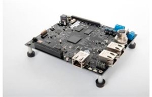
What separates Barr Group’s Embedded Android Boot Camp from other offerings is that students will develop drivers and modify Android for real hardware, testing the software they write on the TI AM335x Starter Kit, not a simulator. And because the AM335x Starter Kit includes an LCD, touchscreen, and a TI Sitara AM3359 processor—which sports an ARM® Cortex®-A8 core and an SGX530 3D Graphics Engine from PowerVR—Barr Group’s course  will also  develop using a very recent version of Android, Jelly Bean. An AM335x Starter Kit is included for every student, making the Embedded Android Boot Camp a great way to ramp up on TI's AM335x processors and software support packages.

As with all Barr Group boot camps, students will find the class very challenging. While knowledge of Linux and Java and ARM processors is not a prerequisite, students must be fluent in C. You can find out what to expect on each day of the boot camp here.

Barr Group’s Embedded Android Boot Camp is offered publicly several times per year—registration is open for the May 4th – 8th class in Detroit, MI—as well as on–site for companies who have a group of students who wish to attend. Visit http://www.barrgroup.com/Training-Calendar to register. 


How Instrumentation Amplifier Vcm vs. Vout plots change with supply and reference voltage

$
0
0
The most prevalent TI E2E™ Community forum question concerning instrumentation amplifiers (IAs) revolves around common-mode voltage (Vcm) vs. output-voltage (Vout) plots. There are typically only a few of these plots in a data sheet based on commonly used power supply and reference voltage configurations. The issue is that the plots depend on the device’s supply voltage, gain and reference voltage. Therefore, if the final application uses power supplies, gain or a reference voltage that differ from those used to characterize the device, the plot will change.(read more)

If you don't scale, you fail: Smaller microcontrollers and systems

$
0
0

 Day 5 of sampling the ultra-low-power MSP430FR6972 FRAM microcontroller and we have our final use-case to explain the value of the scalable FRAM MCU portfolio.

Beyond reducing energy, enabling smarter systems, connecting devices, and increasing security, there is another key area where a scalable portfolio can add value: SIZE. More and more applications are requiring both reduced form factors of microcontrollers and of the full system itself. Some examples include implantable drug delivery systems, or wearable electronics. While not quite on the same scale, both of these examples require efficient design and minimal footprints to meet the needs of consumers.

The MSP430 FRAM microcontroller portfolio offers over 100 options that include several package types and integrated analog and digital peripherals that can help reduce system size. The MSP430FR5738 MCU solves the problem in a more traditional way. It is available in a Die-Size BGA package (DSBGA), which has a very small 2mm x 2mm form-factor.

Another way to reduce size is to look at the system as a whole. Our more full-featured microcontrollers like the MSP430FR6972 MCU, offer a plethora of integrated components that can minimize the size of the complete system. These peripherals include:

  • Comparators
  • Analog-to-digital converters
  • Timers
  • Segment LCD drivers
  • AES accelerators

All MSP430FRx MCUs enable some level of integration, but a full family of microcontrollers means you can expand the functionality of your products with at a minimized cost to your development. To learn more about how the scalable MSP430 FRAM portfolio help you optimize your design, check out the new whitepaper!

New AM437x Industrial Development Kit (IDK) now available

$
0
0

The Sitara AM437x processor family integrates support for industrial protocols for both automation and industrial drives while allowing customers to differentiate their designs with the quad core programmable real-time unit (PRU). The PRU offloads real-time processing from the ARM to manage tasks such as controlling motors.

The AM437x processors enable position feedback control via protocols such as EnDat 2.2 and motor control via fieldbus protocols like EtherCAT in parallel. The quad core PRU in AM437x processors together with other peripherals such as PWM and eQEP allows customers to implement a single chip industrial drive solution.

Evaluate the AM437x industrial automation and position feedback control capabilities with the new AM437x Industrial Development Kit (IDK) available for purchase here for $329

Check out the AM437x Single Chip Drive for Industrial Communications and Motor Control TI Design.

CAN bus arbitration: To yell and back

$
0
0

In the real world, if two people speak at the same time, how do you determine who should speak? Sometimes it’s the one who talks the loudest, and that’s essentially how a controller area network (CAN) bus works.

In a CAN bus, all transceivers transmit the priority of their message (from LSB to MSB); the highest-priority message gets to be transmitted. Specifically for CAN, if two transceivers transmit at the same time, they both are “opening their mouths” to transmit a “0” (logic high); the lower the number, the more important the message. In other words, if two transceivers are “yelling,” the first to “close their mouth” has to wait until the other transceiver finishes transmitting. This whole process is called arbitration (nondestructive arbitration to be exact), which is also what I call any conversation with my father-in-law.

A plethora of robust languages are at your disposal when designing a communications system. Some of them are more mature and well-defined while others are still evolving, such as the CAN bus. CAN is a very robust differential signaling communication protocol. It was originally designed for automotive applications to allow microcontrollers, sensors or other integrated circuits to communicate without the need for a host controller.

The principals of CAN operation make it very robust as well. Its differential signaling topology makes it very resilient to coupled noise. This allows the transmission lines, CANL and CANH, to stay together if there are shifts caused by noise in ground planes. Unlike other differential protocols when CAN is in a recessive state (a logic 1), both lines will rest at the same voltage, typically VCC/2  (unless there is a 3V CAN bus transceiver, which is another conversation entirely).  When the CAN lines are driven apart this becomes a dominant state and a logic 0. Think of the CANL and CANH lines as lips of a mouth: L is your lower lip and H is your upper lip. When you want to communicate, you assert yourself by separating your lips and opening your mouth. This is active low logic signaling, where a “0” is asserted by you speaking. When you are not speaking, your lips are shut tight, causing your CANH and CANL lines to rest together at VCC/2.

Figure 1: CAN signaling and logic levels

Beyond the fundamentals, the CAN bus is evolving. New tweaks and enhanced functionality are making the technology more efficient and unlocking new levels of performance. One of the more recent additions is the idea behind flexible data rates, or FD.

This is lesson No. 1 on how to speak proper “CAN.” You can find out more about CAN FD and our products in a previous blog post, “The need for even more speed: CAN FD.” For the latest and greatest products TI has to offer, check out http://www.ti.com/lsds/ti/interface/can-overview.page.

Additional resources:

Power Tips: Current Mode Control Makes Compensating a Buck LED Regulator Easy

$
0
0
Regulating the current in an LED from a higher input voltage is most efficiently done with a sync-buck regulator.  This can be easily achieved with an integrated FET, peak current-mode controller.In peak current-mode control, the COMP voltage (o...(read more)

SIMPLE SWITCHER® 25th anniversary

$
0
0
It all started with floppy disks. That should give you some perspective on just how long SIMPLE SWITCHER® devices have been making power supply design as easy as it can possibly be.(read more)

How to power FPGAs fast, easy and cost-effectively using a PMIC

$
0
0
If you’re an engineer working with field-programmable gate arrays (FPGAs), you know that they require optimized power sequences for efficient operation. (read more)

World’s fastest 2-D camera uses TI DLP® technology

$
0
0
The majority of us don’t give much thought to individual seconds in our daily lives. But Dr. Lihong Wang, the Gene K. Beare Professor of Biomedical Engineering at Washington University in St. Louis, lives and works one second at a time. Lihong...(read more)

System trade-offs when using delta-sigma modulators and digital filters

$
0
0
Many applications, such as motor drives and power inverters, require isolated measurements of both current and voltage. Although optimized for current sensing applications, TI’s isolated delta-sigma modulators enable high-performance voltage measurements.(read more)

Where’s the gauge? Part 2

$
0
0

Previously, I wrote about why your battery-powered product needs a fuel gauge. If you identified with this need, then you might have looked around to see what gauges are available and thought about dropping one into your design.

Not so fast! I don’t want to scare you, but did you know that you will have to configure and optimize the gauge to match your system and battery? Dare I recommend that you even do some testing and verification to see how accurate the gauge is under your particular use conditions?

“That sounds scary,” you say. Well it could be if you don’t have the right information and tools to do it. So let’s talk about how quick and easy it could be if you did have the right tools. Imagine a graphical user interface (GUI) with a wizard that steps you through some questions and configures the gauge for you. What if that GUI could control a small printed circuit board (PCB) that automatically cycles your battery to optimize and test the fuel gauge while you sleep, or work on other parts of your design? The data from the fuel gauge could be logged, analyzed and plotted to see how it performed. What if you needed no bench equipment at all, and simply plugged this low-cost wonder into the wall while you left it cycling overnight?

Such a PCB does exist, and it’s called the Gauge Development Kit (GDK). Such a GUI also exists, called the Battery Management Studio (or bqStudio for short). Simply connect your battery and target single-cell fuel-gauge evaluation module (EVM) with the GDK and a PC; then you’re ready to automate a learning cycle and perform any arbitrary testing. Constant loads, stepped loads/charges or pulsed loads are easily generated and controlled with scriptable logic.

It’s likely you don’t have much time to become a battery or gauging expert, so TI wants to make it easy for you. Even if you don’t have time to watch our videos at Battery Management University, we think you’ll easily be able to pick up a GDK + EVM + your battery, configure and optimize the gauge, and run some testing to verify the performance for your system and load conditions.

For more about the GDK, check out the GDK tool folder or watch this video. Even without the GDK, you can download a copy of Battery Management Studio and check out its features, then play with a fuel-gauge EVM like our bq27421.

TI has the most open and well-documented gauge portfolio on the market, as well as the easiest to use. Part of that ease of use comes from the tools we provide, so now you shouldn't hesitate to design-in a fuel gauge!

Additional resources:

Precise industrial data acquisition: The heart of the matter

$
0
0

The primary function of nearly every industrial application of electronics is to perform some sort of operation or function (usually with an embedded processor) based on the value of a physical “real world” analog signal. For the embedded processor to do its job, the analog signal must first be converted from analog to digital. Acquiring and converting the analog signal so that its digital representation is as close as possible to the original analog value fundamentally drives the accuracy of the measurement you can achieve and ultimately the performance of your industrial system. This is why data acquisition, or DAQ, is one of the most important subsystems of industrial electronic systems, and the analog-to-digital converter (ADC) is at the heart of the DAQ subsystem. 

Although to us most are hidden in plain sight, industrial systems play an integral role in nearly everyone’s day-to-day activities. For example, take a ride on an elevator. When the doors open, is the elevator perfectly aligned with the building floor? It’s all about the fine-grained accuracy of the motor position, measured by a high-resolution ADC in a DAQ subsystem from an optical analog motor encoder. In modern parts of today’s world, reliable electricity is so ubiquitous that we can easily take it for granted. However, there are industrial electronic systems monitoring the quality of delivered power by constantly measuring voltage and current being delivered to ensure safety and optimal power delivery. The heart of this again is an ADC. Consider an automated production line and all of the sensing complexities such as position, level, temperature and pressure. All of these measurements need to be obtained from various sources, with different electrical requirements, and done so efficiently. This can be easily done with a multi-channel ADC.

If the ADC is the heart of the data acquisition subsystem, the drive signal conditioning that interfaces to the ADC is the coronary artery. It is important to take great care in the design of the input and voltage reference drive signal, to ensure that the ADC’s performance is in top shape and uncompromised by inferior driving circuitry design. See this TI video for a thorough example of how to select an op amp to drive your SAR ADC. It walks you through the steps to design an ADC DAQ signal chain, including theory, calculation, simulation and verification using the ADCpro software.

Thoughtful selection of ADC, op amp and reference drive circuitry will promote a healthy heart in your design and precise data acquisition in your industrial system.

Additional resources:

3 steps to the perfect TI Valentine’s Day date

$
0
0
With Valentine’s Day fast approaching, many of us are probably still looking for the perfect date. By this point, you can’t get a reservation at a restaurant, flowers are overpriced and buying a heart-shaped box filled with chocolates is just...(read more)

Exploring the MSP430 tool chain: Part 1 – MSP430Ware featuring Driver Library makes your design easier

$
0
0

This is the first entry of a five-part series to help you learn more about our robust MSP430 MCU tool chain. This week we focus on TI’s MSP430Ware featuring Driver Library.

Have you heard of TI’s MSP430Ware? If not, you may want to keep reading – because our MSP430Ware featuring Driver Library is about to make your design much easier! Even if you’re familiar with MSP430Ware, continue reading because you’ll be surprised to learn about more features available to you.

MSP430Ware is easy to use and get started because it is integrated into TI’s Code Composer Studio™ (CCS) IDE, or as a standalone package. When delivered as a component of CCS, the MSP430Ware package can be navigated through a sleek GUI within the TI Resource Explorer window. You can import and run examples from Driver Library within the CCS window. MSP430 Driver Library is also available standalone from MSP430Ware as a BSD (Berkeley Software Distribution) software library; you can download the standalone version here.

How to find Driver Library in MSP430Ware

When you open CCS, click ‘View’, then ‘Resource Explorer’. In Resource Explore view, clicking on the MSP430ware icon takes you to the introductory page (shown below). To proceed to Driver Library, click on ‘Libraries’, then ‘Driver Library’ as shown below.

Driver Library is designed for each MSP430 family, currently available for the MSP430F5x, F6x, FR57x, FR5x, FR6x and MSP430i2xx products. Driver Library in MSP430Ware provides full API for those MSP430 device families for configuring, enabling and using integrated peripherals. Each API function is fully documented through a User’s Guide, API Programmer’s Guide and example projects for that family.

Driver Library helps you fly high above bit-wise programming and become an MSP430 MCU expert within minutes. You can call functions in your project or import example projects into CCS directly. You can also take advantage of Driver Library API similarities from one platform to another, which saves you time to design with different devices.

How to import Driver Library to your project

Click on your desired peripheral, for example, Unified Clock System can find ucs_ex1_DCO12MHz, ucs_ex2_VLOSourcesACLK, ucs_ex3_XT1SourcesACLK and ucs_ex4_XTSourcesDCOInternal example projects under UCS. On the right side, you can see options to import, build, download and debug. Choose the example project you would like to use, then click on the “Import the example project into CCS” as shown in screenshot.

If you are looking for the Driver Library of a specific peripheral, just type the name of the peripheral in the search bar of TI Resource Explorer, and then find related example projects categorized by family under Driver Library. Choose the device family, then call the functions or import the code examples directly. Easy-to-understand function calls means less time learning and more time innovating. The MSP430 Driver Library is a great tool to help you write complete projects with minimal overhead and gets your design to market faster!

How to update Driver Library in MSP430Ware

Update your version of MSP430Ware by starting CCS and clicking ‘Help,’ then ‘Install New Software’. This will find any new versions of MSP430Ware with the option to install them.

Another way to update Driver Library is to simply download the file here and unzip into your desired installation directory. Driver Library releases can coexist.

Are you ready to see how you can get to market faster with MSP430Ware featuring Driver Library? Check out MSP430Ware package information and download it now!

Learn more about the MSP430Ware Software Suite in this video:

(Please visit the site to view this video)

Simplify your smart home with smart-me

$
0
0

Five questions with David Eberli, Co-Founder and CEO of smart-me

Smart homes were a red hot topic of conversation at CES this year, causing mass speculation that 2015 may be the year of the smart home. With many startups fueling the connected revolution, we wanted to get the inside scoop from someone at the forefront of the smart home frontier. We asked David Eberli, smart-me’s co-founder and CEO, a few questions about the connected device market, advantages of Wi-Fi® and his relationship with TI.

TI: What is Smart-me?

Smart-me is a multi-purpose technology designed to control and monitor electronic devices. It's an energy and power meter, a remote switch, a time switch, a temperature meter and a lot more all in one device. It connects to your Wi-Fi network allowing you to control and monitor smart-me from anywhere with your smartphone, tablet or computer.

And you have almost infinite possibilities to configure your individual events and actions. E.g. turn power on when temperature is lower than 20 °C.

Smart-me is an easy solution for smart home and smart metering. You can simply combine multiple smart-me devices together to create a smart home system.

TI Avatar

TI: What makes smart-me stand out from its competitors?

First of all smart-me is simple. It's simple to install and simple to use. You don't need any additional hardware. You just need a Wi-Fi network and a smartphone or tablet. Also, you can control it from anywhere. For example, you can control your heater in your holiday home from a few 100 miles away.

A big advantage of smart-me is the quality and accuracy. For the energy metering, we guarantee an accuracy of 1% in comparison to 5 – 30 % of our competitors.

Of course there is the wide range of functionality of smart-me. You can use it as an energy monitor, temperature monitor, remote switch, remote plug, time switch, alarm clock, alert system or just to switch multiple devices on or off together.

And last, but not least, another big advantage of smart-me is the very low energy consumption. Smart-me is designed and built to be as low-power as possible.

TI: There are many wireless connectivity technologies on the market. Why did you choose Wi-Fi for smart-me?   

Wi-Fi has, in comparison to all other wireless connectivity technologies, one very big advantage: Almost everyone has a Wi-Fi network in their home. Because smart-me is cloud based, the devices need an Internet connection. We don't want a customer to have to buy another gateway device, so the easiest solution is to use their (already existing) Wi-Fi network.

TI: Why did you choose TI’s SimpleLink™ Wi-Fi CC3100 wireless network processor and ultra-low-power MSP430™ MCU technology for your product?

First, I'm a fan of TI. I have used TI products for years in projects for other companies (for smart-meters, home control devices etc.) and I was always very happy with them.

When we started the development of the smart-me devices we were looking for a small and cheap microcontroller (MCU) with a very low energy consumption. We found a perfect solution in the ultra-low-power MSP430 MCU.

We choose the SimpleLink Wi-Fi CC3100 device because it has an attractive price, very low energy consumption and it comes with a lot of features. In short, it's the perfect solution for any Internet of Things (IoT) device.

Another reason why we have chosen these TI products was we knew we would receive good support if needed. Every new product has some small issues and it's important that you can ask someone when you have problem.

TI: Where do you see your technology going in the next five years?

The smart home/smart metering market is growing from a small niche sector into a real boom sector and smart-me will be an important part of it. People want a simple solution without any complicated wiring or gateway devices. This is exactly what smart-me is.

Right now we are producing the first series of devices which became available in December 2014 and are already almost sold out.  We are now in our second round of funding so that we can expand to other countries and produce a bigger number of devices. And of course we are always working on new innovative features and already have some similar devices planed.

Additionally, one of our next steps will be to provide an open API, so that others can integrate smart-me in their systems.

For more information visit:

Visit www.ti.com/connectmore to learn how TI is revolutionizing the Internet of Things. 


Rugged linear power management for rugged environments

$
0
0
                If you’re like me, whenever I hear the words “factory” and “automated production lines,” I often think of long conveyor belts, robotic arms and a great deal of movi...(read more)

How an integrated power management IC can simplify your infotainment or ADAS system

$
0
0

The development and expansion and of semi-autonomous and autonomous driving is quickly approaching with the advancement of infotainment and advanced driver assistance systems (ADAS). With HD video, control satellite and over-the-air radio, GPS and mobile device connection and back-up cameras, systems once reserved for only high-end cars are becoming more commonplace.

Yet, this performance is not free. With the increase in performance and processing requirements comes an increase in power requirements for the system-on-chip (SoC) , both in number of rails and current requirements, whether the system is based on TI’s “Jacinto 6” or TDAx SoC families. One way to manage these increased power requirements is to use an integrated power management IC (PMIC).

In these systems, a low-voltage PMIC is supplied by a pre-regulated 3.3V or 5V input. It has all the power rails to power the low-voltage supply rails needed in the system: processor core, graphics core, DDR memory, I/O devices, as well as the analog supplies such as phase lock loops (PLLs) and physical layer devices. Using one IC in place of many to power all of these rails makes both schematic design and layout simpler.

To further simplify the system solution, a low-voltage PMIC like the TPS659039-Q1 integrates more than just power regulation functions. Because the SoCs have many power supplies, they typically have power-up and power-down sequencing requirements that must be met in order to guarantee reliability of the SoC. Instead of using an external microcontroller to sequence the rails, this low-voltage PMIC has hardware-controlled sequencing programmed in to the device in its one-time-programmable (OTP) memory. The OTP not only contains power sequence information but also the boot voltages and other default states. Since different SoCs have different supply voltages and sequence requirements, the same low-voltage PMIC can be used with different OTP programming in order to support a variety of SoCs used in infotainment and ADAS systems.

In addition, automotive environments have strict requirements on electromagnetic interference (EMI), the most common of which is the CISPR25 standard. In order to reduce the EMI from many switch-mode power supplies SMPS integrated in one device, all SMPS are synchronized together so they all use the same switching clock. The default switching frequency is 2.2MHz, which keeps the emissions outside of the AM band, while keeping inductor size small to save board space. This switching clock can be either an input to the PMIC or outputted from the PMIC in order to synchronize all SMPS across different ICs on the same system. This will reduce EMI emissions not only from the PMIC itself, but the whole system.

Do you have questions about other ways PMICs can help your system design?

For more information about these platforms, and technical discussion of power supplies in automotive, please see the following pages:

TI India inspires students to pursue analog

$
0
0
Exciting and inspiring students about engineering is something we are passionate about. At a recent TI Analog Day event on the IIT Delhi Campus in India, we let students in on the secret of how exciting the analog world is and about the many opportu...(read more)

Get cerTIfied, not certi-FRIED! Electromagnetic compatibility testing explained (Part 4)

$
0
0
Welcome to the final installment of this blog series discussing electromagnetic compatibility (EMC) testing. In Parts 1, 2 and 3 we discussed the background of certification testing, as well as the specifications for electrostatic discharge (ESD)...(read more)

How to do a Schematic Review for a low-power DC/DC converter design

$
0
0
A common request from customers in the E2E community is for a “schematic review.” This review also may be called “checking my circuit” or “validating my design.” (read more)
Viewing all 4543 articles
Browse latest View live


<script src="https://jsc.adskeeper.com/r/s/rssing.com.1596347.js" async> </script>