Quantcast
Channel: TI E2E support forums
Viewing all 4543 articles
Browse latest View live

Solving the problems of mechanical buttons and capacitive touch sensors

$
0
0

Have you ever had a button that gets stuck when you press it? Or how about one that won’t go down because something has fallen between the air gaps?

While mechanical buttons can be an inexpensive option for your design, they can sometimes have problems. To solve this, a capacitive touch interface has been incorporated into a vast number of products. However, those can have issues of their own. Have you tried to use these products with gloves or in a noisy area where you can’t hear it register? What about when there are contaminants on the surface?

In order to solve both of these problems simultaneously, we need to look at the pros and cons of both of these types of buttons.

InterfaceProsCons
Mechanical Button
  • User can feel the click of a button press
  • Immune to various environmental conditions
  • Reliability concerns due to physically moving parts
  • Cleanliness issues
Capacitive Touch
  • No button gaps
  • Easily cleanable
  • Input design can be more flexible, variable and clearly labeled
  • User cannot feel the click of a button press
  • Susceptible to issues when exposed to the environment 

These pros and cons can be broken into essentially two categories: feeling the press of a button and press detection reliability.

Feeling the press of a button:

As you may have noticed, the newest smart watches do not have mechanical buttons but instead have users tap to receive a haptic feedback response. This haptic feedback is accomplished with an actuator inside the device. When the device detects a press, the device will simulate the feeling of pressing a button by driving the actuator with a certain acceleration profile that mimics a button press or tap. A number of products, including smartphones, wearables and automotive infotainment equipment, already use haptics to provide a better user experience. A general guide to choosing an actuator for these kinds of applications can be found here.

Press detection reliability:

The best feature of a mechanical button is that it uses displacement to detect button presses. However, that movement is also the factor that causes reliability and cleanliness issues. Although capacitive touch increases reliability by not having mechanical movement this technology can have noise issues when exposed to the environment. To solve this problem, a system that can detect mechanical displacement but doesn’t “really” move is needed. TI has come up with innovative IC solutions with the LDC1000 family.

The LDC1000 is an inductance-to-digital converter that can detect microns of displacement. This technology can be implemented with a number of surfaces, the easiest being a conductive metal.

A complete solution and reference design:

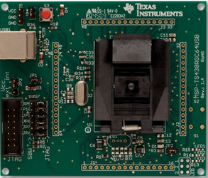
Tying both the haptic and touch technologies together into a complete solution provides a robust, innovative option for designers. The Touch on Metal + Haptics reference design showcases the sleek brushed aluminum design that can be used to create a much better user experience. 

This design will easily drop into a various types of end equipment, such as elevators, point-of-entry keypads and automotive infotainment equipment.The hardware demonstration of this design showcases four buttons to represent a variety of applications for building automation, industrial interface and automotive, to name a few. Each of these buttons interfaces to an LDC1000, where it can measure < 1µm of displacement between the metal and embedded coil in the PCB. Additionally, this reference design showcases two of TI’s advanced haptic drivers. The DRV2605L is a haptic driver for ERMs and LRAs and includes a built-in library of effects licensed by Immersion, built on top of a smart loop architecture for optimum actuator performance. The DRV2667 is a piezo-haptic driver with integrated 105 V boost switch, integrated power diode, integrated fully-differential amplifier and integrated digital front end for higher bandwidth haptic responses.

Want to know more? Visit the detailed TI Designs reference design at www.ti.com/tool/TIDA-00314.

Other resources:


Is your IGBT gate-driver power supply optimized? – Part 2

$
0
0

In part 1 of this series, we discussed how to correctly select the control voltage for an IGBT.  This time, you’ll learn more about the isolation requirements and how to calculate the correct IGBT drive power.

For any industrial motor drive, potential separation of the input circuit (low-voltage) and the output circuit (high-voltage) has to be ensured. The low-voltage side interfaces with the control electronics, whereas the high-voltage side is connected to the IGBTs. The separation is necessary, because the emitter potential of the upper IGBTs is switched between the DC+ and DC- potential of the DC-bus, which can range in the hundreds or thousands of volts. Depending on the application, the corresponding standards for clearance and creepage distance have to be observed as well as compliance with the test voltages. Some typical standards observed are: IEC60664-1, IEC60664-3, IEC61800-5-1, and EN50124-1.

In the simplest case, it may be sufficient to separate only the upper IGBTs of a half-bridge from the lower IGBTs. This is generally possible if the microcontroller is also referenced to the DC- potential. A subsequent separation of the interconnection to the user interface is advised or required, depending on the application. This is mostly to apply basic isolation from noise and common-mode ground effects. In high-power applications, separation takes place at every IGBT, each driver with its own power supply as shown in Figure 1.

Figure 1. 3-phase inverter with isolated gate-drive (Note: All gate-drivers are powered with individual isolated power supplies)

The complexity for the power supply can be simplified for those switched that have their emitter on DC- potential, as shown in Figure 2.

Figure 2. 3-phase inverter with isolated gate-drive (Note: Lower gate-drivers are powered with a common power supply)

Now, lets’ learn how to calculate how much gate-drive power is needed for an IGBT.  While driving an IGBT, the transition between the two gate voltage levels requires a certain amount of power to be dissipated in the loop among gate driver, gate resistors and IGBT. This figure is typically known as “drive power - PDRV.” This drive power is calculated from the gate charge QGate, the switching frequency fIN and actual driver output voltage swing ΔVGate:

PDRV = QGate * fIN * ΔVGate

If there is an external capacitor CGE present (auxiliary gate capacitor), then the gate driver also needs to charge and discharge this capacitor as shown in Figure 3.

Figure 3. IGBTs with gate drive circuitry for gate power calculation

The value of RGE is not influencing the required drive power as long as CGE is fully charged and discharged during one cycle. The required drive power becomes:

PDRV = (QGate * fIN * ΔVGate) + (CGE * fIN * ΔVGATE2)

It should be noted that the drive power does not depend on the value of the gate resistor or the duty cycle as long as the switching transition goes from fully on to fully off and back. Also, these equations are true in non-resonant gate drives. This is the total drive power required by the IGBT but the gate driver which is driving the IGBT also consumes some power.  This power consumption should be added to get the final value for gate drive power.

PDRV = (QGate * fIN * ΔVGate) + (CGE * fIN * ΔVGATE2) + Pdriver

Did this cover what you need to know for optimizing your IGBT gate driver? What more would you like to learn?

Double your current with current-sharing dual LDOs

$
0
0

Given a low-dropout linear voltage regulator’s (LDO) linear operation, it is not unusual to hear them characterized as lossy and/or inefficient. This is true in many cases. Sometimes, it’s an unfair generalization. You need only to look at Equation 1 to see why:

Losses are largely dependent on two variables: VIN and IOUT. (Since VOUT is fixed and IGND is usually relatively small compared with IOUT, they normally cannot be adjusted to improve efficiency.) Adjusting VIN to decrease the VIN– VOUT delta minimizes losses. However, the delta can only be decreased as much as the dropout characteristics of the LDO permit. After that, the only way to further cut losses is by reducing IOUT.

However, decreasing losses in this way is not so simple since we often don’t have any way to reduce the load. A switched-mode power supply can be an advantageous alternative when the VIN– VOUT delta is large enough or when switching noise is permissible. But if the delta is small (ex. VIN: 1.2V, VOUT: 0.9V) or if a clean rail is required (i.e. free from ripple), an LDO is a more desirable choice.The only problem is heat.

To accommodate for heat generated by large loads (ex. 5A), the packaging must be sized and shaped accordingly.1 (Think TO-220.) This ensures that the heat generated via regulation can escape from the die to the board and the ambient environment. Similarly, the board needs to be designed to adequately sink the heat.2 This can be a workable solution but it has several drawbacks:

  • The heat is concentrated on the board. This can problematic when considering how heat can adversely affect other integrated circuits (ICs) and components on the PCB. The heat can easily send another IC over the edge into thermal shutdown if it’s placed too close. The LDO may itself go into thermal shutdown if its local environment is too hot. There is a layout issue: Tying the heat sink to the ground plane can be complicated. Through-hole heat sinks like the TO-220 create holes in the ground path, effectively altering the routing of signals. Surface-mount heat sinks or power pads are preferable as they avoid creating such holes.
  • Higher currents drive up dropout. There is a linear relationship between IOUT and VDO for LDOs. By increasing the load current, the increased dropout may prevent the LDO from regulating at small VIN– VOUT deltas. Figure 1 represents this relationship.


Figure 1: Dropout vs. output current

  • Higher currents drive down the power-supply rejection ratio (PSRR). Although the relationship is not linear, increasing IOUT leads to decreases in PSRR across all frequencies. However, the more damning relationship is between PSRR and how close the LDO is operating near dropout. As the VIN– VOUT delta approaches the dropout voltage, PSRR will drop off significantly due to the reduced gain of the FET. Decreased PSRR can limit the LDO’s ability to adequately attenuate upstream ripple. Figure 2 illustrates this relationship.


Figure 2: PSRR vs. Dropout

I’m happy to say that there is an alternative: current-sharing dual LDOs.

By using two LDOs in parallel we can effectively split the current and the losses between the two ICs. As a result, we are able to address the shortcomings of single-LDO operation:

  • The heat is better distributed. Instead of being concentrated in a single location, the losses incurred via regulation are split between the two LDOs sharing the load. Spreading the heat across the board can be advantageous for the system and lead to simpler PCB design. Figure 3 illustrates this spreading.

Figure 3: Thermal image of Current-Sharing Dual LDOs

  • Dropout is lower. Since the current sourced by each of the individual LDOs is half of what the single LDO would be sourcing, the dropout will be lower. This allows for small VIN– VOUT delta operation.
  • PSRR is better. Similarly, PSRR will improve by virtue of each LDO sourcing less current. Furthermore, as dropout becomes smaller and the VIN– VOUT delta increases, PSRR will improve even more. This translates into a cleaner output rail.

Although the idea of taking two LDOs and placing them in parallel to split current may sound simple, the implementation is more involved than you might think. Simply tying the outputs of the two LDOs together, as depicted in Figure 4, will not ensure equal sharing of current since the LDO with the slightly higher output voltage will dominate and try to source more current than the other LDO. The dominant LDO can easily go into current limit and, possibly, thermal shutdown.

Figure 4: The ideal but flawed approach

Avoiding going into current limit and thermal shutdown requires a method to match the output voltages of both LDOs. One method is to use ballast resistors. This is a simple approach, but it’s not very accurate and the losses incurred via the ballast resistors may be higher than desired. The output voltage is liable to vary by 5 percent or more, especially across load variations.

The other method, recently introduced as a TI design, involves introducing an additional loop to match the outputs. This involves adding an op amp in an open-loop configuration, which compares the currents being sourced into the master and slave LDO and drives the feedback node of the slave LDO accordingly. The benefits of this method are that accuracy is not compromised and that less power is dissipated.

The TI Design describes the logistics of this approach with accompanying details and waveforms. You can also find more information about LDOs at ti.com/LDO.

Additional Resources:

  1. This application note details linear regulator constraints based on power dissipation.
  2. This application note examines the various metrics associated with power dissipation.

Energy storage systems bring the power when it’s needed most

$
0
0
With Lithium-ion battery cell prices dropping and governments incentivizing or subsidizing renewable technology adoption, energy storage systems have emerged as one of the hottest new growth sectors in the battery space. (read more)

Foundational software for functional safety systems

$
0
0

Don’t you love the holidays? All the lights and decorations make it so festive. However, what really drives me crazy is getting all the stuff out of the attic and having to put it back again. It seems like such a waste of time, not to mention it can be dangerous and hard! So, a few years ago I decided to do something about it. Being an engineer, I analyzed the problem and realized the reason I hated it so much was because I had to go up and down the attic ladder with heavy boxes, taking my life in my hands with each step I made .

Of course, there was a very simple solution – all I needed was a lift! I did some Google engineering and found a good design on YouTube and set out to build it. Being a good engineer, of course I defined all the requirements up front and made sure to validate those requirements throughout the development process. Well, not exactly. It actually worked okay the first few times, but a clear design flaw caused the main brace in the attic to fail. When I look back at this experience, I realize the root cause of this was that I didn’t start with the right structural foundation. Doing any type of project, let alone for functional safety applications, you must have a strong foundation to start with.

The answers were right at my fingertips. Instead of going to Google for information, I should have gone to ti.com! If you are developing functional safety applications, the good news is TI has a great foundation to start with. You are probably already well aware of our family of Hercules™ microcontrollers (MCUs) with integrated safety features in hardware, which significantly reduce the amount of diagnostic software you need to develop on your own. This is already a very strong foundation for the development of your safety critical system. On top of that, you still need the foundational software to initialize the Hercules MCU and configure the peripherals to your specific needs. We provide that software with our Hardware Abstraction Layer Code Generator (HALCoGen) and SafeTI™ Hercules Diagnostic Library. Here is the even better news: We also provide SafeTI Compliance Support Packages (CSPs) for both of these foundational software components.

SafeTI CSPs provide documentation, reports, and unit test capability to make it easier for customers to comply with functional safety standards such as IEC 61508 and ISO 26262. The documentation and reports such as safety requirements, safety manual, static and dynamic code coverage are work products produced by following the recently certified SafeTI software development process. A GUI based Test Automation Unit (TAU) based on LDRAunit is also provided to allow customers to execute and extend the included unit level test cases. The CSPs can also provide a helpful starting point (foundation) for customers who need to provide similar evidence for their functional safety software.

We’re excited to provide these SafeTI CSPs to assist customers by providing a foundational example for their functional safety software development, whether they are building a new lift for their garage after holiday festivities or taking an industrial or automotive system through certification. I’m all set for the holidays next year. What about you? Leave us a note below and let us know—what type of system that you work on could benefit from these CSPs?


For more information:

Delta-sigma ADC basics: How the digital filter works

$
0
0
Designing with a delta-sigma analog-to-digital converter can help achieve the highest possible resolution in your system. But to maximize this architecture’s benefits, it helps to understand how the delta-sigma modulator and digital filter in t...(read more)

Out of Office: Engineer by day, firefighter by night

$
0
0
TIers do amazing things every day at work and when they are out of the office. In our ongoing series, ‘Out of Office,’ we showcase the unique and fascinating hobbies, talents and interests of TIers all over the world. Most of his colleagues...(read more)

Where’s the gauge? Part 3

$
0
0
Once you realize that you need to at least give your user some basic indication of your Li-Ion battery’s state-of-charge, you might also realize other features and benefits that a fuel gauge can offer. (read more)

Working towards a smarter grid at DistribuTECH 2015!

$
0
0

Another DistribuTECH has come and gone! Last week the TI Smart Grid & Energy team was on-site in San Diego to showcase the latest in grid infrastructure – we hope you had a chance to stop by our booth to get a first-hand look at our products. 

In case you missed us, we demonstrated a full spectrum of end-to-end solutions for grid monitoring, protection and communications.  The majority of our demonstrations were based off TI Designs reference designs which include complete system designs comprising of hardware, and software to help smart grid developers get to market quickly.  Some of our key demonstrations included:

Analog front-end (AFE) for Merging Units and Multi-function Protection Relays: This solution addresses the front-end needs of merging units where measurement of multiple current and voltage channels are required.  Read more.

Isolated Shunt-based Current Measurement: This isolated shunt-based current measurement design enables high accuracy current measurement without the need to use isolated current sensors such as the current transformers (CT).  Read more.

Branch Current Monitor Measurement Module: This reference design is designed to measure only branch current and is created for accuracy across the majority of the rated current range while at the same time being cost efficient. Read more.

Hybrid RF + PLC Communications: This hybrid RF + PLC communications demo is a preview of the hardware coming soon to TI which brings the highest performance AMI network technology and high speed, low latency for substation communications.  Read more at www.ti.com/smartgrid

IEC 61850 Breaker Failure Demonstration: A low-cost, simplified implementation of an IEC 61850 Substation Bay Controller is demonstrated by running the Triangle MicroWorks IEC 61850 stack efficiently on the Sitara™-processor-powered BeagleBone Blacks with a Linux target layer definition. Read more.


Overall, the team had a great week at the show and can’t wait for what the year ahead will bring for the smart grid and energy industry. For more information about our Smart Grid & Energy solutions, visit www.ti.com/smartgrid

Inductive sensing: Should I measure L, RP or both?

$
0
0

When devices offer different types of measurement capabilities, it’s important for designers to consider which measurement is best suited for their use case.Some inductive sensing solutions, like TI’s LDC1000inductance-to-digital converter (LDC), have two measurement capabilities:

  • RP-measurement: The LDC measures the equivalent parallel impedance of the sensor at its resonant frequency by measuring the energy loss of the sensor due to magnetic coupling with a conductive target.
  • Inductance (L)-measurement: The LDC measures the resonant frequency of the sensor, which is a function of sensor inductance, also influenced by magnetic coupling with a conductive target.

Some LDCs, such as the LDC1000, even offer both measurement capabilities.

Having these two measurement capabilities leads to a few questions:

  • Do you always need to measure both parameters?
  • If you only need one, which one should you choose?

Let's compare the two measurement types and explore a few different use cases.

Sensing range and precision

The maximum sensing range is similar for L- and RP-measurements and depends primarily on coil diameter, resolution of the LDC and device configuration. A useful rule of thumb for precision applications is that an LDC requires a coil diameter of at least twice the maximum sensing range (for example, we would need a 20 mm diameter coil to measure a target distance up to 10 mm). This applies to both L-measurements and RP-measurements.

Figure 1. Axial position sensing

Reference clock input

Inductance is measured by determining the oscillation frequency shift when the conductive target approaches the sensor coil. As a result, it requires an accurate and stable reference clock. RP-measurements do not rely on an accurate reference clock and the LDC1000 can perform RP-measurements without an external reference clock. This is an advantage in situations where a reference clock is not available, or where number of wires between the LDC and the microcontroller must be minimized.

Temperature

Temperature drift in L-measurements is small compared to the temperature drift in RP-measurements. When using a high-Q sensor, which helps minimize temperature effects, temperature compensation in L-measurement applications is typically only required when you need very high precision over a wide system temperature range.

On the other hand, the resistivity of any metal has a known but significant temperature coefficient, which becomes relevant in RP-measurements. For example, the resistivity of copper changes by 3900 ppm/°C, aluminum by 3900 ppm/°C and iron by 5000 ppm/°C. To account for the change in resistivity, temperature compensation is typically required for most applications that employ RP-measurement.

Spring compression applications

Compressing, extending or twisting a spring changes its length, diameter and/or number of turns, which in turn changes the spring inductance. Therefore, measuring inductance directly, rather than RP, is the obvious choice for this application.

Figure 2. Spring compression measurement

Metal composition applications

Inductive sensing can be used to differentiate between different types of metals. In such applications, an L-measurement provides information on the permeability (μ) of the metal, because the inductance of the system is greater with greater μ of the metal. By contrast, an RP-measurement provides information on the resistivity (ρ) of the metal.

As eddy currents flow through the conductive target, the induced electric energy is dissipated based on the value of ρ. This is indicated by a change in RP. By generating a table of inductance and RP at a fixed distance from the coil, we can identify different metal alloys. To detect metal composition, we need to measure RP and L simultaneously.

Metal choice

Most metal types can be equally well-measured with L or RP. However, there are some magnetic materials where the L response at certain frequencies is significantly smaller than the RP response. For those materials, RP is a more appropriate choice. We will cover this topic in more detail in an upcoming blog post.

Which measurement approach will you use?

For most applications, you may prefer the reduced system design complexity of L-measurements due to lower temperature effects. There are two exceptions, in which RP measurements are  required: systems in which no accurate reference clock is available and selected designs use magnetic materials as a target. And metal composition detection demands measuring both parameters simultaneously.

Additional resources:

Instrument clusters: moving beyond chimes and dings

$
0
0

The instrument cluster is the main means to display information and status of vehicle systems and drive conditions. What was once a basic display, now includes gauges for various parameters, indicators and status lights as well as displays and sometimes sophisticated acoustical effects.

Depending on the target customer base, the instrument cluster audio subsystem can be implemented in multiple ways. Higher-end systems prioritize higher sound pressure level (SPL), audio quality and reliability, while cost is a top priority in lower-end systems.

SPL

Higher SPL helps overcome interior noise, particularly at high road speeds. SPL is directly related to the output power delivered by the speaker and to the output power delivered by the audio amplifier. At constant speaker impedance, the power delivered to the speaker by the amplifier depends on the amplifier’s efficiency and voltage.

  • In terms of efficiency, Class-D amplifiers have the upper hand (compared to Class-AB amplifiers). Class-D amplifiers can deliver substantially higher efficiency levels in the 80-90 percent range, whereas Class-AB amplifiers can deliver 30-40 percent and require more complex thermal management.
  • A higher-voltage amplifier typically delivers more power and is more likely to withstand the high-voltage transients typical in automotive systems.

Audio quality

Automotive original equipment manufacturers (OEMs) increasingly demand higher audio quality to provide a tailored user experience that enhances brand recognition and affinity.

Audio quality specs depend on the amplifier’s total harmonic distortion (THD) and the signal chain’s signal-to-noise ratio (SNR) and dynamic range (DR).

Reliability

Automotive applications are known to demand higher levels of reliability compared to personal electronics applications; AEC-Q100-qualified devices offer a high level of reliability tailored for automotive applications.

In addition, Q100-qualified audio amplifiers with integrated diagnostics and protection take reliability to an even higher level. For example, audio amplifiers with integrated diagnostics can signal to an external microprocessor whether the speaker has been disconnected or has its terminals shorted to each other, to ground or to its voltage rail.

Integrated diagnostics are particularly important during car assembly to ensure that the sound system has been properly installed and that no shorts occurred during speaker installation. Also, this feature can help ensure that safety-related systems, like instrument clusters and other telematics that alert users of out-of-the-ordinary conditions, are continuously operational.

Cost

Much has been said about how Class-AB audio amplifiers are more cost-effective than their Class-D counterparts. When considering the IC by itself this may be true; but  system designers must consider the cost of the whole audio solution.

For example, the fundamental differences in efficiency between Class-AB and Class-D audio amplifiers has an impact on the audio solution cost. The lower-efficiency Class-AB amplifier requires more complex and expensive thermal management. Expensive heatsinks and an additional printed circuit board (PCB) area for thermal dissipation are very common downsides to using Class-AB amplifiers.

To be fair, Class-D amplifiers require an external inductor that adds some cost to the solution, but with recently released automotive-grade, low-cost inductors, Class-D amplifier inductor cost can be minimized. With this in mind – and with instrument clusters being a very space-constrained application – Class-AB amplifiers are no longer the preferred audio solution, as Class-D amplifiers offer higher system performance at a comparable total solution cost.

The TAS5421-Q1 is designed for these applications. As a Class-D amplifier, it minimizes solution size while simplifying thermal management. Its fully integrated diagnostics and protection capabilities reduce bill-of-materials (BOM) cost and (most importantly) enhance system reliability. The TAS5421-Q1 is also compliant to the CISPR 25-L5 automotive electromagnetic interference (EMI) specification.

A higher-voltage Class-D audio amplifier, like TAS5421-Q1, is not the only topology used in instrument clusters. Other possible topologies include discrete protection/diagnostics and the use of step-up and/or step-down converters. I’ll discuss these topologies in greater detail in a future blog post, so be sure to subscribe to the Behind the Wheel blog to stay in the loop.

Additional resources:

  • Keep in mind other TI audio devices for an instrument cluster, like the TAS5421-Q1 or TLV320DAC3100-Q1.
  • Explore other TI devices suitable for instrument cluster applications in this system block diagram.
  • Use this audio selection tool to narrow the search for the right audio amplifier for your needs.
  • Join the TI E2E Audio Community to search for solutions and share knowledge with fellow engineers and TI experts. 

Implementing transition-mode control using UCD3138 devices

$
0
0

A while ago, I was asked to examine the feasibility of generating closed-loop control waveforms needed for operation in transition mode using the TI UCD3138 controller. These digital controllers are very flexible and equipped with a lot of bells and whistles. I was curious to see what I could come up with.

Figure 1: Transition mode control

Transition-mode waveforms do not look like the typical pulse-width modulation (PWM) waveforms, since both the duty cycle and the switching period are changing. They are also not like LLC or phase-shifted waveforms supported by the UCD3138. Therefore, none of the standard modes of PWM output modulation will generate what we need.

What is unique about transition-mode control is that you should start the next switching cycle on time based on what happened in the previous switching cycle – not sooner and not later. This on-time switching of next-pulse ON provides one of the following two advantages:

  • Valley switching. Turn off the field-effect transistor (FET) just when the current crosses the zero line and start the next switching cycle after a measured and fixed delay. The voltage should be quite low at that point, avoiding large switching losses.
  • Zero voltage switching (ZVS). Turn off the FET just after the current crosses the zero line. The current will be slightly negative; this way, after a certain controlled time delay, the voltage will decay to zero. You could turn the FET on again and start a new switching cycle. But the delay time is a function of Vin and Vout, so it needs periodic adjustment.

On the face of it, both of these ideas seem to be easy to implement with a digital controller like the UCD3138. It has several analog comparators with adjustable reference voltages that can dictate when to terminate the pulse driving the FETs.

Being a microcontroller and firmware-based device, the firmware can adjust the reference to the analog comparator and regulate the delay based on the analog-to-digital converter (ADC) measurement of input and output voltages and currents.

But how can we terminate a pulse and start a new cycle when an analog comparator toggles? Termination of the pulse resembles the cycle-by-cycle (CBC) or peak-current mode (PCM) current limiting by pulse truncation. Should we use the CBC mechanism that already exists in the UCD3138? How do we end the switching period and start a new pulse? The sync input signal can do that, but can it truncate the pulse as well? After all, if a sync event happens when the digital PWM output is high, it will cause a pulse extension; the pulse will stay high until the next switching cycle. Should we connect the analog comparator to both CBC and sync signals?

Here’s a trick that will eliminate the need for CBC: Configure Event4 (EV4) as zero or a very small number at the beginning of the switching period. This way, the sync signal terminates the switching cycle and resets the digital PWM counter. EV4 is engaged immediately after this reset; therefore the pulse is truncated as well. It’s like killing two birds with one stone.

Figure 2: Transition mode current and voltage waveforms

Now we need a delay to let the negative current decay and the voltage go to zero, and then turn the primary FET on exactly at this time in order to achieve ZVS. This time interval between the end of the period and the time to turn on the FET can be achieved by calculating the placement of Event1 (EV1).


Based on calculations, the delay time between end of the period/the start of a new pulse (Tr) and the negative current detection threshold (IN) can be calculated by:

When Vin ≤ Vo/2, no negative current is needed.

where IN = 0 and ω = 245 nS.

When Vin > Vo/2, a negative current IN is needed to allow the value of Vds to reach zero volts at the valley point.

I used a spreadsheet to generate a lookup table that I entered later as part of the firmware to adjust the value of Tr and IN accordingly.

The above look-up table is a simplified way of transition-mode control implementation using the UCD3138. If you use external comparators for current crossover detection, you are all set. But the UCD3138 happens to have several internal analog comparators. How can we utilize one of those comparators for this application?

The problem is that most members of the UCD3138 family of controllers do not offer an external analog comparator output. So the analog comparator output cannot connect to the SYNC pin directly. I was able to come up with a workaround to overcome this, but I will save you from the details here.

Zooming out to see the bigger picture, we have actually implemented many topologies and configurations that were not envisioned by the systems or design group when they defined and designed the UCD3138.  

Yet the flexibility of this digital controller allows us to use it in applications, such as a solar micro-inverter, a bi-directional automotive DC/DC, a totem-pole power factor correction (PFC) and much more.

In case you are interested in getting more details for implementing, such as a transition transition-mode scheme using a UCD3138 controller or discussing the feasibility of any other configuration besides the ones already announced and published by TI’s power management group, please comment on this blog. For all TI digital power products and solutions, visit: www.ti.com/digitalpower

Exploring the MSP430 tool chain: Part 2 – How well do you know the MSP430 target boards?

$
0
0

This is the second entry of a five-part series to help you learn more about our robust MSP430 MCU tool chain. Don’t miss Part 1 on this blog from last week, because this week we focus on MSP430 target boards.

Have you ever heard of our target socket boards? Target boards are breakout development kits for your MSP microcontrollers that include a socket for a specific package and pin count that enable you to add your own hardware. Target boards are available for all MSP devices and feature a ZIF target socket for interfacing with various pin-outs and package types. Each target board comes with a JTAG connector.

The benefit of a target board is that you can remove the microcontroller, thus you evaluate different devices in the same package with only one target board! All the pins are exposed to header, so you can easily measure or connect to other things. If you’re new to the MSP430 MCU portfolio, feel free to check out the target boards we have, available at the TI Store! You can see a full list of our target boards at the end of this blog.

In addition to the target boards, we also offer the MSP-FET programming/debugging tool. The MSP-FET430Ux Design Kit bundles feature the MSP-FET with a standalone target board. This bundle can be used to program and debug the MSP430 MCU in-system through the JTAG interface or the Spy Bi-Wire (2-wire JTAG) protocol. The design kits can help you integrate an MSP MCU into your application and enable full system debugging.

 So why are you still waiting? Try the MSP430 target boards today and get your design started right now!

Socket Pin-Count

Target Board & Programmer

Target Board Only

MSP430 MCUs Supported

8-pin

MSP-FET430U8

MSP-TS430D8

MSP430G2210, MSP430G2210

14-pin

MSP-FET430U14

MSP-TS430PW14

MSP430F20xx, MSP430G2x01, MSP430G2x11, MSP430G2x21, MSP430G2x31

MSP-FET430U092

MSP-TS430L092

MSP430L092

24-pin

MSP-FET430U24

MSP-TS430PW24

MSP430AFE2xx

20-/28-pin

--

MSP-TS430DW28

MSP430F11x1, MSP430F11x2, MSP430F12x, MSP430F12x2, MSP430F21xx

MSP-FET430U28

MSP-TS430PW28

MSP430F11x1, MSP430F11x2, MSP430F12x, MSP430F12x2, MSP430F21xx

MSP-FET430U28A

MSP-TS430PW28A

MSP430F20xx, MSP430G2xxx

32-pin

MSP-FET430U32A

MSP-TS430RHB32A

MSP430i20xx

38-pin

MSP-FET430U38

MSP-TS430DA38

MSP430F22xx, MSP430G2x44, MSP430G2x55

40-pin

MSP-FET430U40A

MSP-TS430RHA40A

MSP430FR572x , MSP430FR573x

MSP-FET430U23x0

MSP-TS430QFN23x0

MSP430F23x0

MSP-FET430U40

MSP-TS430RSB40

MSP430F51x1 , MSP430F51x2

48-pin

MSP-FET430U48

MSP-TS430DL48

MSP430F42x0

--

EM430F5137RF900

CC430F513x

MSP-FET430U48B

MSP-TS430RGZ48B

MSP430F534x

MSP-FET430U48C

MSP-TS430RGZ48C

MSP430FR58xx, MSP430FR59xx

64-pin

MSP-FET430U64

MSP-TS430PM64

MSPF13x, MSP430F14x, MSP430F14x1, MSP430F15x, MSP430F16x, MSP430F16x1, MSP430F23x, MSP430F24x, MSP430F24xx, MSP430F261x, MSP430F41x, MSP430F42x, MSP430F42xA, MSP430E42x, MSP430FE42xA, MSP430FE42x2, MSP430FW42x

MSP-FET430U64D

MSP-TS430PM64D

MSP430FR4xx, MSP430FR2xx

MSP-FET430U64A

MSP-TS430PM64A

MSP430F41x2

MSP-FET430U64USB

MSP-TS430RGC64USB

MSP430F550x, MSP430F551x, MSP430F552x

FET430F6137RF900

EM430F6137RF900

CC430F614x

MSP-FET430U64B

MSP-TS430RGC64B

MSP430F532x, MSP430F530x, MSP430F5310

MSP-FET430U64C

MSP-TS430RGC64C

MSP430F522x, MSP430F521x, MSP430F523x, MSP430F524x, MSP430F525x

80-pin

MSP-FET430U80

MSP-TS430PN80

MSP430F241x, MSP430F261x, MSP430F43x, MSP430F43x1, MSP430FG43x, MSP430F47x, MSP430FG47x

MSP-FET430U80USB

MSP-TS430PN80USB

MSP430F552x, MSP430F551x

MSP-FET430U80A

MSP-TS430PN80A

MSP430F532x

100-pin

MSP-FET430U100

MSP-TS430PZ100

MSP430F43x, MSP430F43x1, MSP430F44x, MSP430FG461x, MSP430F47xx

MSP-FET430U100B

MSP-TS430PZ100B

MSP430F67xx

MSP-FET430U100C

MSP-TS430PZ100C

MSP430F645x, MSP430F643x, MSP430F535x, MSP430F533x

MSP-FET430U100D

MSP-TS430PZ100D

MSP430FR69x

MSP-FET430U100USB

MSP-TS430PZ100USB

MSP430F665x, MSP430F663x, MSP430F563x

MSP-FET430U100A

MSP-TS430PZ100A

MSP430F471xx

MSP-FET430U5x100

MSP-TS430PZ5x100

MSP430F543x, MSP430BT5190, MSP430SL5438A

128-pin

MSP-FET430U128

MSP-TS430PEU128

MSPF677x,       MSP430F676x, MSP430F674x, MSP430F677x1, MSP430F676x1, MSP430F674x1


One to Watch: Rising Star Manish Bhardwaj

$
0
0
In our ongoing series, ‘One to Watch,’ we profile the movers and shakers at TI who are making a difference through their extraordinary work. Simply looking at how TIer Manish Bhardwaj tackled a recent project exemplifies why he’s...(read more)

Change is constant!

$
0
0

Things are really cooking in my world. My new focus moves into providing you with the best analog design tools through the WEBENCH® Design Center. Soon you will see a very useful amplifier circuit design tool that will provide fully-defined circuits, a bill of materials (BOM), and a simulation environment.

As I said, change is constant! Now you can look forward to seeing my future blogs on TI’s very popular Analog Wire blog, where I will join my colleagues who have been posting a couple of times a week on signal chain technology and design tools. All previously published On Board with Bonnie posts will continue to be available via our archive on the TI E2E™ Community, allowing you to further investigate the various analog tangents through which I have passed in the last few years. I look forward to blogging on Analog Wire and hope you enjoy my contributions as much as I enjoy writing them. Be sure to look for my first Analog Wire post on March 11, 2015. See you there!


Wireless power coils: Let’s wrap!

$
0
0
For most electrical engineers – even those familiar with the details of analog circuit design – magnetic components can still seem a bit mysterious. (read more)

Get Connected: How to extend an SPI bus through a differential interface

$
0
0

Welcome back to the Get Connected blog series here on Analog Wire. In my previous Get Connected post, we examined using a general-purpose serializer/deserializer (SERDES) to aggregate multiple data inputs from different sources for high-speed transmission in short-reach or long-haul applications. In this post, I’ll look at extending a serial peripheral interface (SPI) bus through a differential interface, which can be useful when designing systems that support remote temperature or pressure sensors, for instance.

In SPI applications, the master and slave are relatively close to each other, and the signals typically never travel off the printed circuit board (PCB). SPI signals are single-ended, transistor-to-transistor logic (TTL)-like signals that can run up to 100Mbps depending on the application. An SPI bus consists of four signals: system clock (SCLK), master out slave in (MOSI), master in slave out (MISO) and chip select (CS). The master provides the SCLK, MOSI and CS signals, while the slave provides the MISO signal. Figure 1 shows the bus architecture of a standard SPI bus.

Figure 1: SPI bus

What if you need to send your SPI signals off-board from your microcontroller or digital signal processor (DSP) to a remote board that contains an analog-to-digital converter (ADC), a digital-to-analog converter (DAC) or another device? This can be challenging for several reasons. Signal integrity becomes a big concern due to reflections caused by unterminated signal lines. The characteristic impedance of the transmission media and termination impedance will differ substantially, causing an impedance mismatch on the bus. The result will be a standing wave of energy that radiates from end to end on the bus, causing communication errors. Electromagnetic interference (EMI) is also a concern as the high-frequency portion of the SPI signal radiates outward, allowing the signal to couple onto adjacent signals.

There is a simple solution to this problem, however: differential signaling. Differential transceivers like the SN65LVDT41 and the SN65LVDT14 take the SPI signals and convert them to low-voltage differential signaling (LVDS). LVDS works well in SPI applications due to its noise immunity and bandwidth. A previous Get Connected blog post reviewed the fundamentals and benefits of LVDS; you can find it here.

The architectures of the SN65LVDT41 and the SN65LVDT14 allow for the entire SPI bus to be translated to LVDS: four transceivers in one direction for MOSI, SCLK and CS and one transceiver in the opposite direction for MISO. The LVDS chipset also has the added benefit of built-in termination, making implementation simple and reducing component count in applications where board space is at a premium. Figure 2 shows the makeup of an extended SPI bus architecture using the aforementioned chipset. Shielded twisted pair (STP) CAT5 cable is not a requirement for such an implementation, but it is rather a nice to have given its ease of implementation.

Figure 2: Extended SPI bus

Figures 3, 4 and 5 show the performance of the SN65LVDT41 and SN65LVDT14 transmitters at 100Mbps across multiple lengths of CAT5 cable. The receivers in the SN65LVDT41 and SN65LVDT14 support a 200mV input threshold tolerance, which is easily met by the transmitters at these distances and speeds.

Figure 3: 8-meter CAT5 100Mbps TX waveform

Figure 4: 15-meter CAT5 100Mbps TX waveform

Figure 5: 25-meter CAT5 100Mbps TX waveform

For answers to common questions on solving interface design challenges in your application-specific solutions, check out the TI E2E™ Industrial Interface Community to read Search posts from engineers already using TI interface products, or create a new thread to address your specific application. If you’re not connected, you can get connected with TI’s broad interface portfolio that spans and links together a wide range of interface standards and applications.

Please watch for my next post in the Get Connected series, where I’ll discuss a multipoint LVDS (MLVDS) device with extended ESD performance that meets the International Electrotechnical Commission (IEC) 61000-4-2 specification. In the meantime, read about extending SPI and McBSP with differential interface products in this app note.

Leave your comments in the section below if you’d like to hear more about anything discussed in this post, or if there is an interface topic you'd like to see us tackle in the future. And be sure to check out the full Get Connected series. 

For better or for verse

$
0
0

A class on poetry just in time for Valentine's Day 

There is not a single engineering student who has not tried to compose a few lines of poetry at some stage in his or her life.  Come on, admit it, you have tried it too.  If you have been successful, well that is fantastic, but if you are poetically challenged, this blog will most certainly help you.

For people who are not natural cooks, there is canned food. For people who are not natural poets, there is canned poetry. Try this easy recipe. The first two lines of the poem are always the same – ‘Roses are red, violets are blue.’ The remaining two lines must be filled out by you. There you go, you already have your first poem!

Roses are red,

Violets are blue,

The remaining two lines

Must be filled out by you.

Using the italic fonts makes the poem look even more poetic.  Italics were invented by the romantic Italians. My daughter recently told me that so obsessed were Italians with the italic font that they even made the tower of Pisa lean.

Poetry 101

Valentine’s day is a perfect time to start writing poetry.  Having taught a class on ‘How to write papers,’  I have decided to take on the challenge of teaching ‘Poetry 101 for Engineers.’  My method is to teach through examples. 

Let’s see now, you are an engineering student in a lab and you are wiring up a circuit. Just this once you forget that VDD and GND cannot be connected together.  That is when you might be inspired to write the following.

Roses are red,

Violets are blue,

I tied VDD to Ground

And smoke my circuit blew!

Logically Speaking

We engineers are so fond of zeros and ones  - isn’t that the truth? Here is a verse that may make sense if your Valentine is as appreciative of logic as you are.

Roses are red,

Violets are blue,

If Zero went to a bar

He will certainly emerge True!

You are a student of Computer Science who went to buy movie tickets for you and your Valentine. You have just learnt about dequeuesor double-ended queues where items can be dropped at any end of the queue. Naturally, you attempt to join at the counter-end of the long line and, by golly, those computer-illiterate people in the line give you a mouthful.  Here is how you may express your exasperation:

Roses are red,

Violets are blue,

The line outside the theater

I found out is not a dequeue.

A Perfect Gift for your Valentine

If you are considering gifting anMSP430 MCUto your Valentine, the following card will be a perfect accompaniment:

Roses are red,

Violets are blue,

For a genius like you,

An MSP430 MCU!

It’s the thought that counts

If you are planning to share your best WEBENCH® power designs with your Valentine (well, it's the thought that counts), make sure you at least tell her/him about the benefits of the WEBENCH design and simulation environment –

Roses are red,

Violets are blue,

WEBENCH can do circuits

And it can do systems too!

OK, that’s plenty. These examples should have illustrated how easy it is for an engineer to compose poetry. Your assignment is to turn in a poem of your own.I leave you with a final example for those of you who are a participant in theTI Innovation Challenge Design Contest,

Roses are red,

Violets are blue,

Take TI’s innovation challenge

Just think of something new!


For more Valentine's fun be sure and read: 

3-steps to a Perfect TI's Valentine's Day Date

A Heart of Electronics for Valentine's Day

Happy Valentine's Day to you and yours!

TI’s ADAS team takes the automotive industry by the wheel in 2014

$
0
0

2014 was a great year for the Advanced Driver Assistance Systems (ADAS) System-on-Chip (SoC) team at TI, not to mention a busy one. From the announcement of the TDA3x to winning multiple awards for our family of processors, needless to say we are quite thrilled with what we accomplished so we thought a quick recap of the year’s highlights was necessary.

  • April- The team introduced the availability of the Vision Software Development Kit (SDK) that offers developers a flexible framework, comprehensive set of hardware device drivers and a useful set of development tools for more efficient implementations of ADAS on TI's heterogonous architecture. Additionally, the team announced that libraries are available for both its Embedded Vision Engine (EVE) and digital signal processor (DSP) on the TDA2x System-on-Chip (SoC). The libraries include more than 200 optimized functions for both EVE and DSP libraries, providing customers and third parties with the building blocks to jump start development and reduce the time to market. Check out the press release here.
  • July- The ADAS team was pleased to announce that they had surpassed shipment of 15 million SoCs in a broad range of ADAS applications including front camera, surround view and radar. Now sold through over 15 Tiers and on the road in over 100 car models with over 25 OEMs, TI SoCs are truly enabling the automotive industry to redefine advanced driver assistance systems.  The team was also awarded 2014 Frost & Sullivan Product Leadership for Semiconductor Solutions.  Read more here.
  • Oct.- The introduced of the newest member of the automotive SoC family, the TDA3x solution. The TDA3x processor family is designed to help car manufacturers develop sophisticated ADAS applications that meet or exceed EuroNCAP requirements, reduce collisions on the road and enable a more autonomous driving experience in entry- to mid-level automobiles.  The TDA3x shares a scalable architecture with the higher performance TDA2x device family announced one year prior, enabling entry to mid performance applications such as front camera, surround view and fusion.  TDA3x also enables entry to high performance radar and small form factor smart rear cameras with an innovative package design.  Additionally, our TDAx SoC Family has been recognized as a 2015 CES Innovation Awards HONOREE in the newly introduced Safe Driving product category. The CES Innovation Award Team said the TDAx, “scored highly across all judging criteria, and it joins a small percentage of other products that are given this honor each year.” For more details click here to read the release and watch videos of the demos.


  • Dec.- In early December the team received fabulous news (even though it wasn’t announced until January) by being honored with an Electronic Products’ Product of the Year award for its TDA3x solution. Jim Harrison, editor at Electronic Products said, “TI's rich heritage in automotive and ADAS-related application development lets the company understand and address key goals in the automotive market. ADAS technologies pose some tough challenges for design engineers and the TDAx unique features will be instrumental in enabling advanced safety - and, one day soon, an autonomous vehicle.”

Even though 2014 was very busy and full of great accomplishments, the ADAS team cannot wait to show you what is in store for 2015.

Make sure to stay up to date with the latest ADAS offerings on our landing page and Behind the Wheel blog.

SAR ADC response times: Interface topology makes a difference (Part 2)

$
0
0
In my previous blog post, I explained a simple serial interface in which each data bit is transferred as it is resolved. I also noted that this type of interface is usually restricted to lower resolution or lower speed. Most of the modern, high-resolution (>12 bits) successive approximation register (SAR) analog-to-digital converters (ADCs) employ redundancy and error-correction techniques to improve the performance of the ADC, especially at higher throughput rates. In such ADCs, the final conversion result is available only after the entire conversion process is complete.(read more)
Viewing all 4543 articles
Browse latest View live


<script src="https://jsc.adskeeper.com/r/s/rssing.com.1596347.js" async> </script>